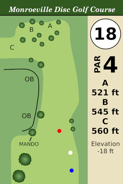
Remade the signs for the Monroeville disc golf course. These will be printed and posted on each hole. Here are the white tee signs.


.
NES Programming with cc65
Remade the signs for the Monroeville disc golf course. These will be printed and posted on each hole. Here are the white tee signs.
.
This is about NES 6502 assembly programming (nesdev) and might be difficult to do in C. If you came here for C programming, then this page is not for you.
What is an IRQ? It is a signal that interrupts the normal CPU operation. For NES development purposes, it is for something that is time sensitive and needs to happen immediately. Like the MMC3 scanline counter. If you need a screen split at exactly scanline 63, you set the MMC3 mapper to count the scanlines, and when it reaches 63, it sends the CPU an IRQ signal. When the CPU gets an interrupt signal, it immediately jumps to the IRQ handler. (the handler would then change the scroll position, or whatever you need to happen).
Even without a special mapper, the NES has 2 built in IRQs, generated by the APU (audio) : The Frame Counter IRQ and The DMC IRQ.
.
If you turn this on, an IRQ will fire once per frame. Roughly. The APU and the PPU are not synced and they have no idea what the other is doing, and the APU “frame” is just slightly slower than the PPU. Anyway… what could we do with a once per frame IRQ? At least one game (Dragon Quest ?) uses this to run its music code. If you have your music code tied to your NMI handler, then it will stop running if you happen to turn off NMIs. But, if it is placed in the IRQ handler, then it will continue to run regardless of whether NMIs are on or off (like when you are loading the next level of the game).
How could we do this?
CLI will allow IRQs to happen. Put that in the INIT code. Then,
turn on Frame Counter IRQs (this is Mode 0. I’m pretty sure that Mode 1 doesn’t trigger the IRQ).
LDA #$00STA $4017
The you need an IRQ handler. Make sure you save and restore any registers that you change. Make sure you exit with RTI (not RTS).
For the Frame Counter IRQ, you need to acknowledge the interrupt signal, or else it will immediately loop back to the IRQ handler over and over in an endless loop.
IRQ: pha ;save all the registers txa pha tya pha bit $4015 ;this reads 4015, acknowledge the IRQ jsr Music_Code pla ;restore all the registers tay pla tax pla rti
You don’t need to worry about the status flags. The RTI will automatically restore the status flags.
One interesting note about IRQs – when the CPU gets an IRQ signal, it temporarily sets the interrupt disable flag. And when it sees the RTI instruction, it automatically restores the interrupt disable flag (ie. clears it, because we got here because it was clear). And an important point… you SHOULD NOT change the interrupt disable flag inside the IRQ handler. SEI is pointless, because the RTI will just clear it again. CLI could crash your game, because it will just immediately jump back to the IRQ handler in an infinite loop. If you need to turn off IRQs inside the IRQ handler, it should be done by turning off the source of the IRQ, such as LDA #$40 STA $4017 for the Frame Counter.
I don’t personally advocate for using the Frame Counter IRQ. I’m just explaining it for academic reasons.
BTW, it is possible to sync the APU frame to the PPU frame (with or without the IRQ on). If you write $c0 to $4017, it should reset the APU frame. You could do that inside the NMI handler (once per frame) and it should sync them (sorry, I haven’t tried it). I’ve heard that several major Nintendo made games do this. If you do this, I believe you are supposed to put the APU frame in mode 1 (5 step), and with Frame Counter IRQs off. I don’t know why you would want to do this, but the engineers at Nintendo seemed to think it was a good idea. Or, maybe this is an example of Cargo Cult Programming, where one guy did a thing, and it seemed to work, and they copied it for a bunch of projects even though they didn’t really need to.
.
This is the useful one. So, DMC is one of the audio channels. It can play sound samples (low quality sound samples). If you turn on DMC IRQs and play a sample, when the sample ends it will send an IRQ signal.
What can you do with this? You can time a mid-screen scroll split. You could time multiple screen splits. Another idea – normally you would use a sprite zero hit to time a screen split, but repeatedly polling for the sprite zero is a waste of CPU processing, so you could have a DMC IRQ happen just before the sprite zero hit, and you wouldn’t waste so much time looking for it.
About the multiple screen splits though… it won’t be exact. It’s not as pixel perfect as the MMC3 IRQ. The APU runs the DMC channel with a slightly variable lag. The best you can do is narrow it down to a range of about 3-4 scanlines. So you would want the screen split to happen where there isn’t much going on and you have the same color all the way across the scanline, for several scanlines in a row. I just grabbed a random title screen that has blank scanlines.
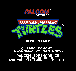
Between Palcom Software and the TMNT logo, you could do a split. Between Push Start and 1990 you could do a split. Etc. Anywhere you have several blank scanlines you could do a screen split with the DMC IRQ. Or maybe if you like crazy graphics, you could do it where there isn’t blank scanline area and you’d get some crazy glitchy mid screen splits. If you’re into that sort of thing.
Another problem is that you won’t be able to use the DMC channel for any musical purposes. And you will have to reserve some space for a blank DMC sample (all zeros, for example). Well, it wouldn’t need to be very big, so that’s not much of a concern. But, if I had a screen where not much happened and I wanted multiple screen splits, I would probably used TIMED CODE. That’s just a block of code that doesn’t really do anything, except that it uses a very specific amount of time to execute. With TIMED CODE, you could get exact scanline splits. But, let’s show how the DMC IRQ works, just for fun.
CLI will allow IRQs to happen. Put that in the INIT code. Then somewhere in our NMI code we would put the rest of the IRQ setup. First, we shut off the DMC channel, because you can’t trigger a new sample if it’s currently playing a sample. Just to be sure, we turn off that channel.
LDA #$0fSTA $4015
Then, turn on DMC IRQs
LDA #$8f ;IRQ on, not looped, rate of FSTA $4010
Set the rest of the DMC settings…
LDA #$C0 ; ROM address $f000STA $4012 ; tells where the "sample" isLDA #$02STA $4013 ;sample length, 2 = $21 bytes longLDA #$1fSTA $4015 ;turning the DMC channel back on will trigger the "sample" to play
I put sample in quotes, because it should just be a block of zeros. 21 hex is 33 decimal. So… 33 zeros.
Rate of F and length of 2 will take 126 scanlines, so we could time for a screen split in the middle of the screen with this. See the chart at the bottom for other possible timings.
https://www.nesdev.org/wiki/APU_DMC
This page will also explain the DMC registers, and the formulas to calculate address and length of the samples.
Then we need an IRQ handler.
IRQ: pha ;save all the registers txa pha tya pha lda #$0f sta $4010 ;turn off DMC IRQs, to acknowledge the IRQ ;screen split code here pla ;restore all the registers tay pla tax pla rti
Alternatively, we could leave DMC IRQs turned ON and set up another DMC IRQ inside the IRQ handler.
I don’t think we need the LDA #$0f STA $4015 beforehand, because the sample should have ended already, so the APU is ready to play another sample. The LDA #$1f STA $4015 will reset the timer and start playing the blank sample, so we won’t get another IRQ until that sample ends.
;set up whatever DMC settings you need for the next splitLDA #$1fSTA $4015 ;DMC on, will trigger another IRQ
If you have multiple scanline splits, you might need multiple versions of the IRQ code, and use some variable to direct your code to various options. I would assume that if you are advanced enough in 6502 asm to write an IRQ handler that you would also be able to write a case/switch in assembly.
LDA #$0f STA $4015 would also work to acknowledge the DMC IRQ (stop another IRQ from firing), and that would work in place of the LDA #$0f STA 4010 above. I think any write to $4015 will acknowledge the IRQ.
.
Oh, and one more consideration. I said to trigger the DMC IRQ inside the NMI handler. However, NTSC NES consoles (US and Japan) and PAL NES consoles (Europe) have different timings, and PAL consoles have longer V-Blank periods. If you want your code to work on both kinds of systems (timing mid screen scroll splits) you will have to adjust the timing for the 2 different types of system.
.
It should be noted that if the CPU ever sees opcode zero (00 = BRK) that it will jump to the IRQ handler. They share the same vector, so both IRQ and BRK will jump to the same location.
Computer systems that use the 6502, such as Apple ii and Commodore 64, sometimes use BRK as part of the code, and you would then put the BRK handler in place of the IRQ handler.
Interestingly, some NES games actually use BRK as part of their programming. If you do this, it should be noted that BRK doesn’t put the return address on the stack, but return address +1, so you need to put a byte after the BRK and then the next line of code after that. Also, there is a bug in the NES, where an NMI signal at the exact same moment as a BRK signal, the BRK will be ignored and it will go to the NMI handler instead. Probably advisable to not use BRK except as an error handler… because if your code runs into a zero, then something has gone terribly wrong.
…anyway…
How does our IRQ code know if we handling a BRK, or a Frame Count IRQ, or a DMC IRQ? You can actually tell the difference. Inside the IRQ handler, read from $4015, and bit 7 (1000 0000) will be 1 if it is a DMC IRQ. Bit 6 (0100 0000) will be 1 if it is a Frame Count IRQ. Both will be zero if it is neither (and probably a BRK).
.
Some mappers generate IRQs. MMC3, MMC5, VRC4, VRC6, VRC7, FME-7, and Namco 163. I believe the Rainbow mapper has an IRQ. The Famicom Disc System has an IRQ. And the Expansion Port has an IRQ line (although I don’t think anyone has ever used it).
Monroeville Park East
Updated April 2026. They just put in concrete pads. The only major change is to hole 6. They appear to be putting in a 3rd pin placement (for everything but 10), but by April those haven’t been placed yet.
THIS PAGE IS OLD INFORMATION. HERE IS A LINK TO THE NEW UPDATES…
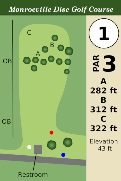
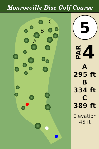
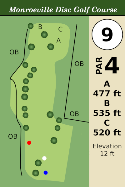
I was bored and made up some maps of each hole. Oh, and here’s a printable map of the whole coarse.
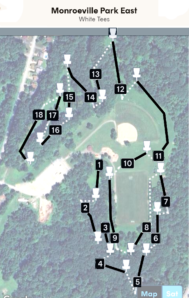
Monroeville DGC is a mixture of wooded and open holes. It’s very hilly. The only water is a creek that runs from the right of hole #1, crosses in front of the white tees on #2, and then goes along the far right side of #2 fairway. There is one bathroom by the #1 tees (not open during the winter).
Note that on each basket is little plastic tabs which show the direction to the next tee.
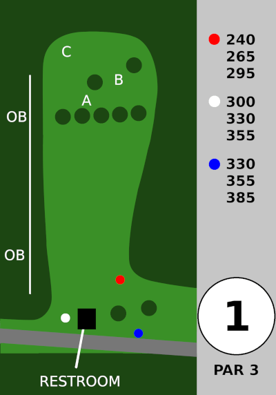
Hole 1 – is a steep downhill, sloping left to right. There is OB left, but the real danger is the rough on the right. There’s usually a left to right headwind that likes to toss discs deep into the ravine to the right.
.
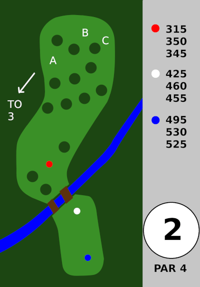
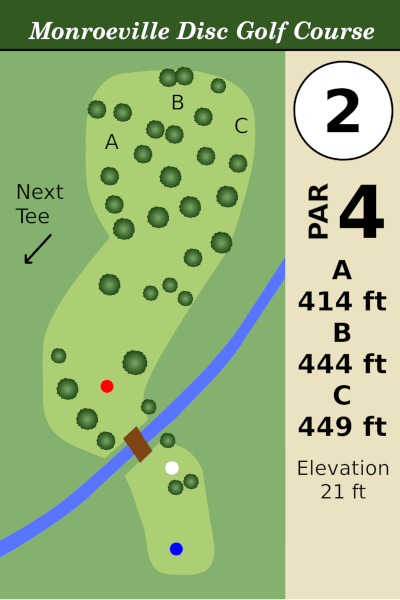
Hole 2 – They just put in a big walkway over the creek to get to the white tee. You have to climb up a ways to get to the blue tee box. From the red tee it’s an uphill shot.
Backtrack a bit to get to the #3 tee.
.
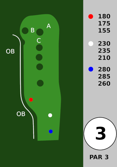
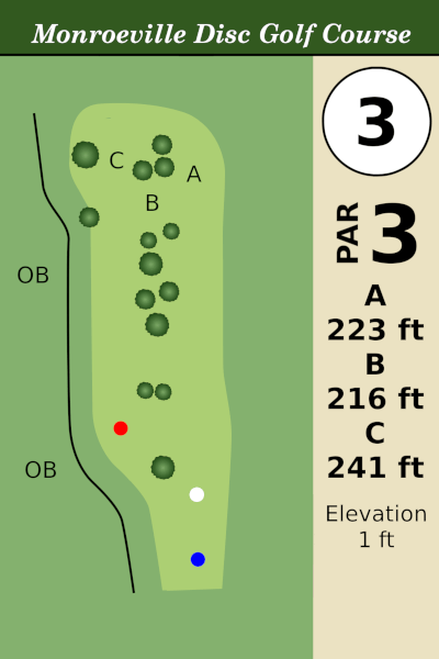
Hole 3 – is short and straight. OB left. There’s a little path near the A basket down to hole 4, and you do NOT want your disc to roll down that path. I did it once, and it rolled over a 100 ft.
.
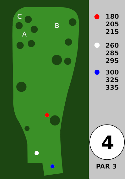
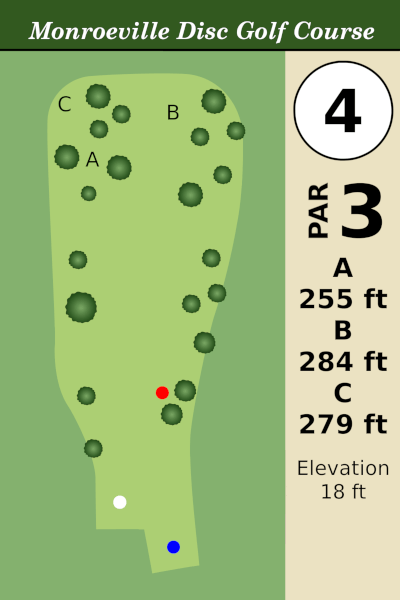
Hole 4 – is a steep uphill. You might not be able to see the pin from the tee.
.
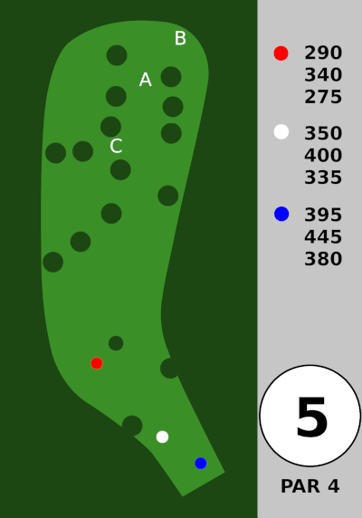
Hole 5 – is a steep uphill. I think you’re better off landing on the right side of the fairway. They moved the long pin (B) further to the right to accommodate the new hole 6 tee pads.
.
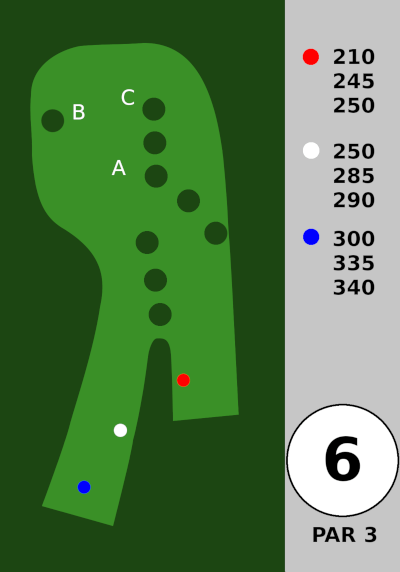
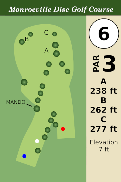
Hole 6 – Slightly uphill, curving left. They just moved the white and blue tees. You might not be able to see the basket from the white or blue tees, but you definitely want the disc to hook left and not go too far right.
.
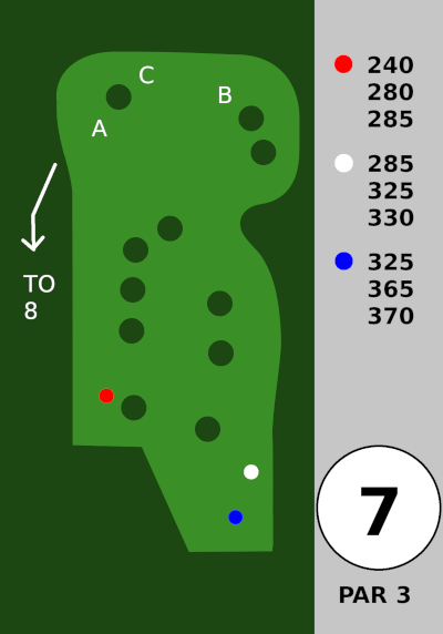
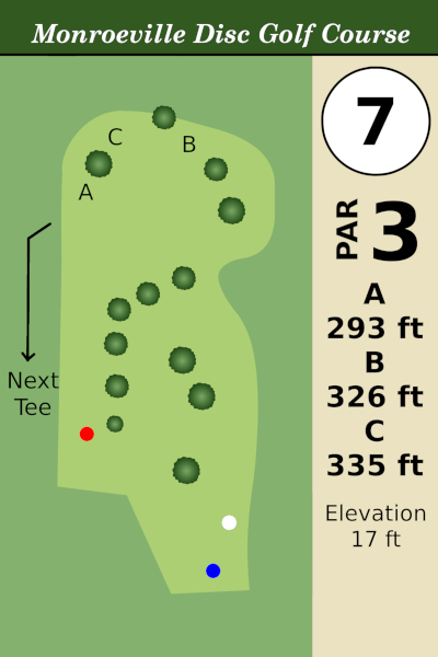
Hole 7 – Red tee is a tunnel shot to an open area. White and blue tees you either forehand through the middle of the fairway or backhand down the far right. Regardless, the far right side is to be avoided.
Backtrack a long way along the soccer field to get to the #8 tee.
.
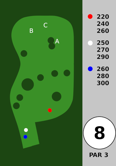
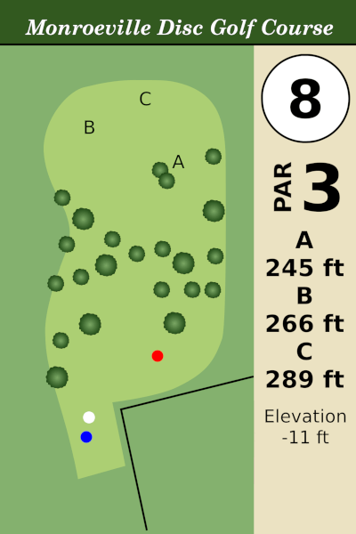
Hole 8 – has a lot of trees. There’s usually a headwind. Aim for a low ceiling shot between the trees, or (from the white / blue tees) you could potentially go OVER all the trees.
.
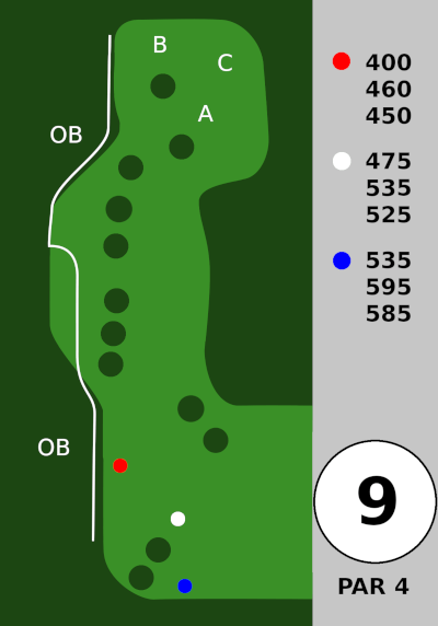
Hole 9 – is a long, narrow, side-sloped (right to left) fairway with OB left. Tee shot, just doesn’t fade hard left. 2nd shot is a bit uphill and the baskets are on top of a hill. The OB line is very close to basket B, making it much harder than A. This hole is probably the hardest to birdie.
.
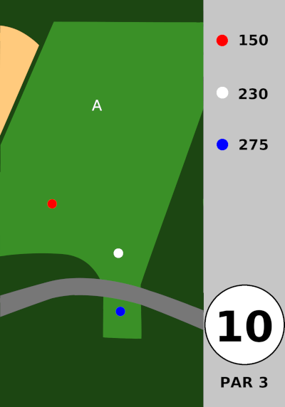
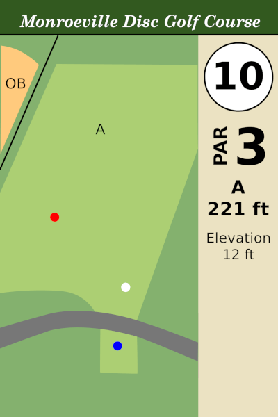
Hole 10 – Next to the baseball field. No trees. This seems like it should be very easy, but due to the elevated basket and the wind, it is not.
.
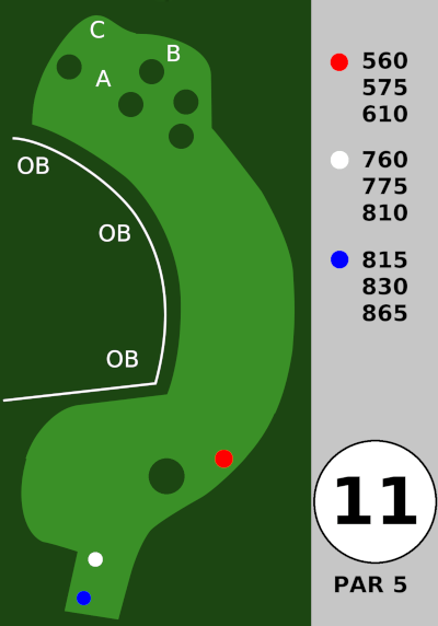
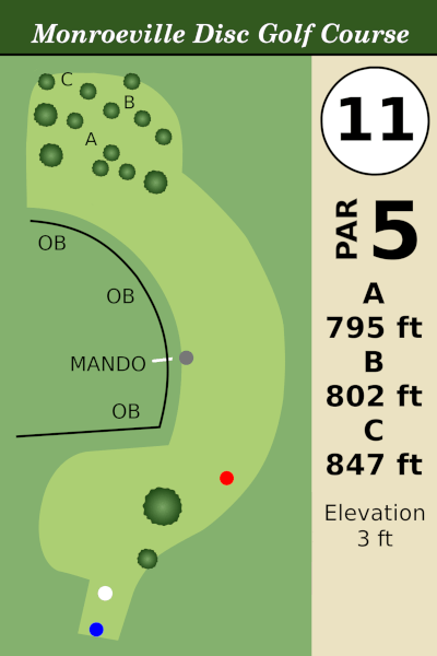
Hole 11 – The baseball field is OB, but you are allowed to throw over the field, as long as you don’t land on it. Once you get in front of the red tees, you need to curve left. The fairway is hard to see. Here are some pictures.

From the white tees it’s 200 ft to clear the tree on the right and 240 ft to the hill. The arrow here will get you to the center of the fairway. You could also land on the hill, by the fence.

From the red tees, aim just to the right of this light pole.
.
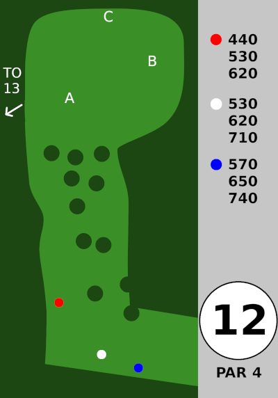
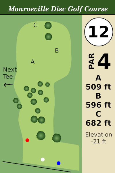
Hole 12 – The first half is thick with trees. The left path is wider and easier. The right path is doable, just don’t sail too far right or you’ll never find your disc. Over the top gets riskier every year as the pine trees get taller… I don’t recommend that play anymore.
From the end of the trees, it’s 120 ft to the A basket and about 200 ft to the B basket (and maybe longer from the far left side).
.
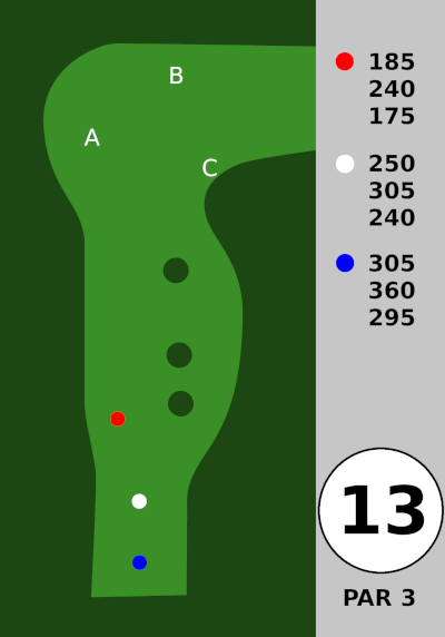
Hole 13 – is a straight par 3. Don’t go too far left, or there is a steep downhill (very easy to lose your disc). Don’t try to climb down, just walk all the way around back to 12 fairway to get it. It has very elevated baskets which makes birdies more difficult, but the surrounding trees help block the wind.
.
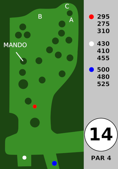
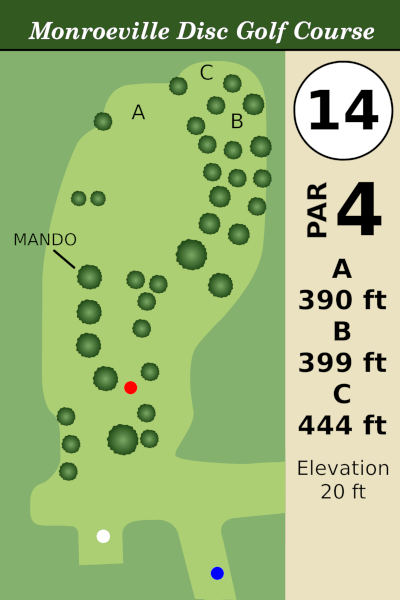
Hole 14 – is a steep uphill. Mando tree on the left. There is a little open fairway just passed the mando tree. The blue tees are way back down a path by a small building (headed back to the ball field).
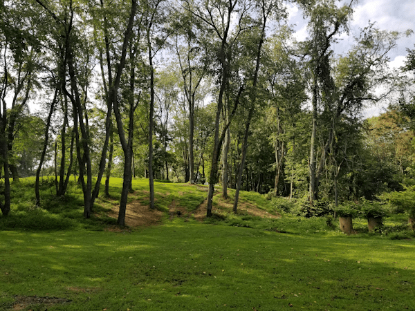
This is the view from the WHITE tee at 14. I usually take the right gap with a high hyzer off the tee.
.
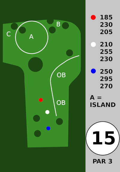
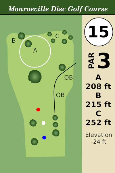
Hole 15 – is downhill, while avoiding that one huge tree. If the basket is inside the white circle, play as an island, and everything outside is OB. I believe there is a drop zone marked with a pink flag.
If the basket is at B or C, only the 17th fairway to the right is OB. Caution, going too far long is bad. It’s a really steep drop off back there.
.
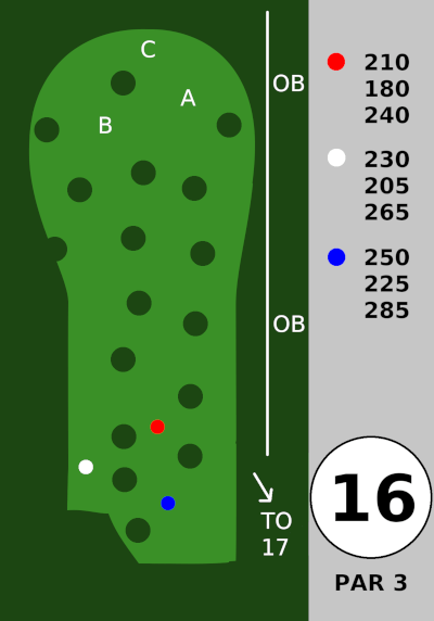
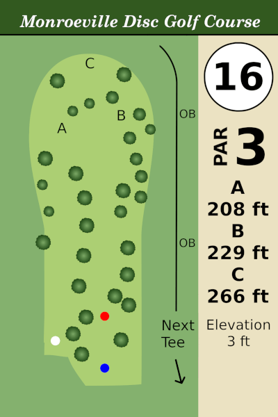
Hole 16 – is a par 3 with a ton of narrow gaps between the trees. OB to the right, and steep downhill to the left. The slope and the bare ground cause discs to skip far left, so aim for a landing spot a bit to the right of the basket.
Backtrack to the right to get to the next tee.
.
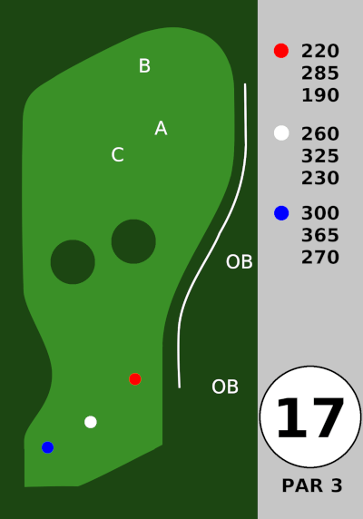
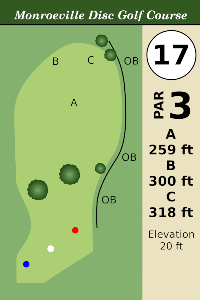
Hole 17 – is a steep uphill, with OB along the right. This plays much longer than the numbers say.
.
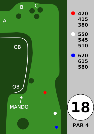
Hole 18 – is one of the hardest holes, and OB left is very easy to find. There is a mando tree, way on the left, but I can’t imagine how you could miss it. From the tee, just try to land in the fairway. Then, you need an overstable disc to curve hard left and down towards the basket. It’s very downhill by the baskets. Rollaways near basket A frequently go all the way down to the parking lot, so maybe try to go long/wide on that 2nd shot and get stuck in the rough near basket B to avoid deadly rollaways.
.
I will need to remeasure once they put in the C pins.
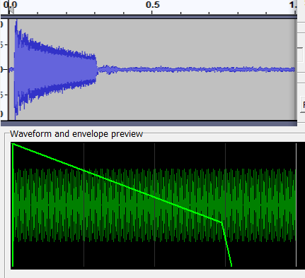
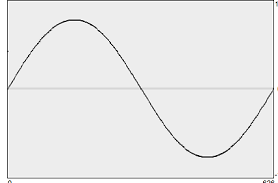
I was experimenting with SNESGSS, and I noticed that the ADSR envelope sounded different than I expected. Look at the Instrument Tab, and see the AR, DR, SL, SR levels. The preview image draws a line to show you what the envelope should look like.

But, it never sounded what it looked like… so I ran some tests. I think you will find the results interesting.
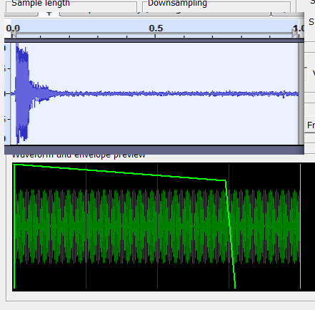
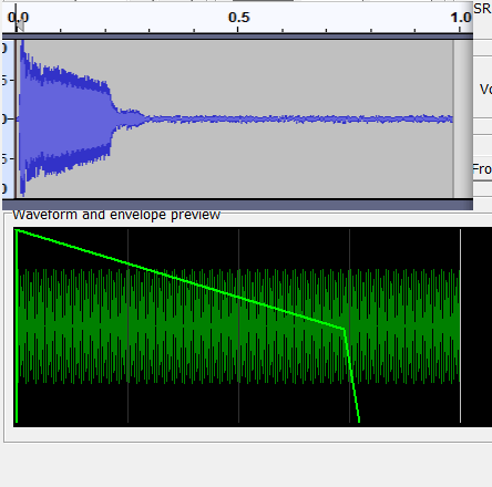
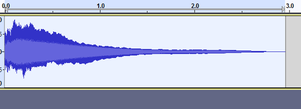
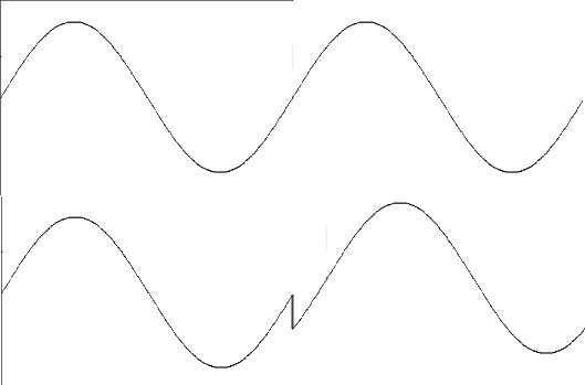
With AR =15, DR = 1, and SR at 30, I adjusted the SL (sustain level) and then recorded the result from my actual SNES.
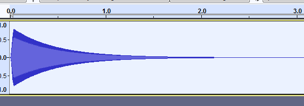
(Top pic is the actual recording, and bottom pic is what SNESGSS showed.) Interestingly, the audio from SNESGSS was fairly close to correct. It’s just the drawing of the envelope that is incorrect.
With SL = 7, it skips the decay phase.

.
.
Here’s with SL = 6.
.
.
Here’s with SL = 5.

.
.
Here’s with SL = 4

.
.
Here’s with SL = 3
.
.
Here’s with SL = 2
.
.
Here’s with SL = 1

.
.
And, here’s with SL = 0

The last one here is pretty close to what I would have expected.
.
I don’t fully understand what’s going on, or why the result was so different than expected. It seems to me that the decay period is much shorter than the graph would lead you to believe. This is with DR = 1, which is the 2nd slowest decay rate. For most of the tests the decay period finished very quickly. With SL at 6 or above, it was nearly instant.
This also underscores the point… you need to test your songs on a real SNES.
.
(NOTE – AR and SR were tested separately, and seems to be correct).
.
.
Back in the 90s, the SNES vs Genesis debate was raging. Sega would say “blast processing” over and over and that’s all people remembered. Look how fast Sonic moves! Of course, scrolling speed has nothing to do with CPU speed. You could have ported Sonic over to the SNES with no trouble, and he would run just as fast. The idea of “blast processing”, I guess, was that the CPU was faster. According to this page (below), though, the Genesis CPU was really only about 20% faster than SNES.
https://segaretro.org/Sega_Mega_Drive/Hardware_comparison
But SNES was leaps and bounds above the Sega Genesis in every category. More colors. More layers. More sprites. More modes… mode 7 graphics. Etc. etc.
Music is a toss up. SNES was sample based, so it could produce sounds that actually sounded like real musical instruments. However, it had a filter that made the audio sound muffled and cut a lot of the high end out of the sound. Sega Genesis had the FM audio, which was limited but had a big bright full sound all through the full spectrum. Maybe too bright… as many of the soundtracks come across as a bit annoying in their instrument choices (usually using the subpar default instruments given to the musician, using the GEMS tracker that Sega gave all the developers). But some of the tracks really sound great. I can’t decide which was better, but most people say that SNES was better sounding.
Before I go on a tangent though, back to graphics…
So, SNES had more sprites, but very few games needed more than 80 sprites anyway. SNES had more colors, but if you play the same game on both systems, they don’t look THAT different. So, I began to wonder if SNES really was better looking. Let’s investigate. I chose these games specifically to highlight the difference in graphic ability.
First the Sega Genesis (Mega Drive) version. Notice the dithering on the face. When you have fewer colors to choose from, you have to dither to get the mid tones.

And then the SNES version. I chose this because I knew it was using the 256 color mode. Notice the face is nice and smooth due to many more colors to choose from. The screen is narrower because the Sega version is in 320 pixel mode (40H), where the SNES version is 256 pixel wide.

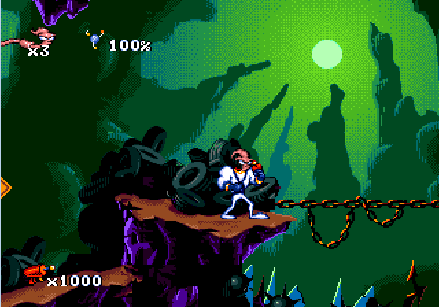
Another game that was released on both systems. Lets look at this intro scene where he’s surfing on a 7-up bottle.

And see the difference with the SNES version. More subtle coloring on the bottle. You might miss it, but you can see the Color Math used for transparency as part of the bottle blends 50% with the ocean behind it.

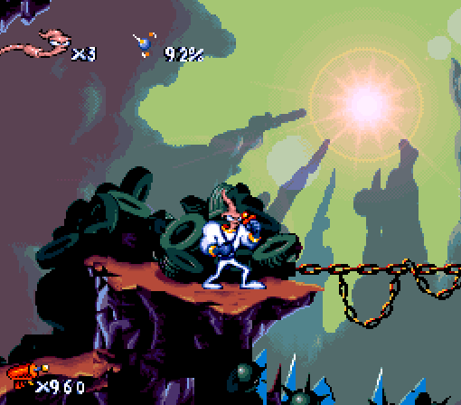
Again, the Sega Genesis version first. I like this. There is some amazing pixel art going on here, and it looks great, even with the dithering.
The SNES version uses its 3rd layer for a whole different effect. It’s using Color Math to create a lens flare that moves around with the character. The screen is narrower again, which has a negative affect on gameplay (not being able to see what’s coming up next). The colors are a little different. I kind of like the high contrast of the Sega version, but the SNES version looks higher quality.
I think it’s pretty clear that having more colors makes the game look better. I looked at a few other games, and the difference wasn’t so much. You could show me a clip of one at random, and I probably wouldn’t be able to tell which system it was from. But in general, the SNES versions look better.
(On a side note, I’ve heard people say that Earthworm Jim’s soundtrack sounds better on the Sega Genesis. I don’t know, you decide.)
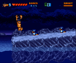
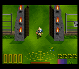
The SNES, depending on mode, has more layers than the Sega Genesis. The most common SNES mode (mode 1) has 3 layers, vs Sega Genesis had 2 1/2 layers. I say 1/2 because it had something called a “window” which was a non-scrolling layer that was always on the same plane as Plane A. Usually, it was used for a scoreboard (HUD). Ok, you have only 2 layers, but then I saw a game which appeared to have a lot more than 2 layers. In Sunset Riders, about 10 minutes in, you are riding on a train.


The scoreboard/HUD is using the window.
The top of the big mesa is using sprites that move in unison with it. The 2 cacti are using sprites at different priority levels (one is behind Plane A and one is in front of Plane A).
And, of course, Plane A and Plane B are scrolling at different rates, and that is all there is too it. Just a bunch of simple tricks to make 2 layers seem like 5.
.
But, can’t you do the same thing with SNES? Yes. SNES has layer priorities and sprite priorities so that 3 layers can seem like 5.. 6.. 7… maybe more, layers. But, the point I was trying to make was to show that a little creativity can make the limitations much less limiting.
So, who wins the console wars? Does it really matter? As long as the game is fun, I don’t thing the player is going to be counting colors or worrying about whether or not there is a 3rd layer. Just have fun. That’s what matters, anyway.
Most SNES games use Mode 1 most of the time. It gives you 2 layers of 16 color per tile, and 1 layer of 4 color per tile. All the other blog pages cover Mode 1, and I think we’ve talked enough about that. Let’s take a look at examples of games using the other modes.
(4 layers of 4 colors per tile)
The only advantage is the extra layer. (Well, also the graphics are half the size in this mode.) Very few games use this except for screens of text. (Final Fantasy 2, US)


This is similar to Mode 1, but with only 2 layers of 16 color per tile. This is an Offset-Per-Tile layer, meaning that the screen can ignore the scroll value and instead have a unique scroll value per column (it should really be called offset-per-column). I will talk about it a little more below.
Yoshi’s Island really makes good use of this mode in the “Touch Fuzzy Get Dizzy” level.

Tetris Attack uses Mode 2 to raise the game board as you play.

Another Mode 2 example is Shin Nekketsu Kouha – Kunio-tachi no Banka. The bridge moves in waves.

Mode 3 has 1 layer 256 color and 1 layer 16 color per tile. You see it a lot in title screens and cut scenes. Personally, I think this has the highest quality images. The graphic files are 2x as big (8 bits per pixel instead of 4 bpp). One advantage of this mode, you don’t need to align graphics to a grid. All tiles have use of all colors in the palette.

Though, you almost never see games use Mode 3 for actual gameplay. I found only 1 game that does: NBA All-Star Challenge.

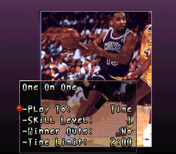
If you are going to use mode 3 with sprites, you need to reserve some colors for the sprites… so technically the BG graphics should use maybe 128 colors, because sprites need to use the 2nd half of the CGRAM.
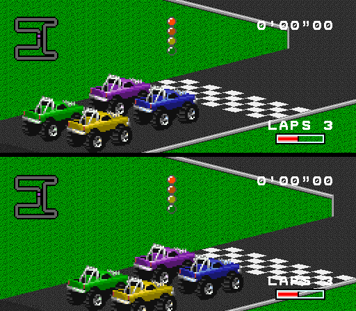
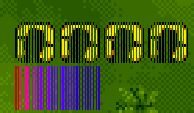
Another Offset-Per-Tile mode. You get 1 layer of 256 color and 1 layer with 4 color per tile. This is rarely seen, and only one game I know uses the offset OPT system. Bust-A-Move uses it for regular gameplay, and only to slightly jiggle the pieces once in a while. But any other time the pieces move (like when they fall), they are sprites.

A few other games use Mode 4 without using the Offset-Per-Tile. I guess they wanted the second layer to use 4 color graphics instead of 16 colors (like Mode 3).
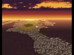
This mode is an option for any 256 color layer (such as Mode 3, 4, or 7), to ignore the palette and use the graphic data as an RGB value itself (R3,G3,B2 plus each tile can add another R1,G1,B1). It’s actually lower quality than standard 256 colors, so it was almost never used, except for this map in ActRaiser 2.

This is the High Resolution Mode. 1 layer of 16 color per tile, 1 layer of 4 color per tile. It has these weird 16×8 tiles which squish down into 8×8 on screen giving a sharper image (double the horizontal resolution). The graphics would have to be twice as big (takes up 2x as much VRAM). This mode was rarely used, and typically only for the text of some Japanese only games. Romancing Sa-Ga 3.
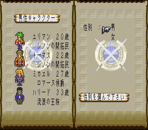

You might notice that the upper right 3 boxes aren’t quite as sharp as the rest of the screen (like the guy with headphones on). Those are sprite graphics. High Resolution only affects backgrounds.
I haven’t found an example of this. It is a HiRes mode with 1 layer of 16 colors per tile. It also has Offset-Per-Tile mode, like mode 2. No game uses this mode.
I just want to point out that I did some testing, and old CRT TVs tended to blur a bit, and didn’t really have the ability to generate 512 pixels wide, so the final result was not nearly as good as I was expecting. That would explain why so few game developers used the High Resolution modes.
However, emulators do a much better job, so maybe these modes could work for future homebrew development. One option, to get around running out of VRAM space, would be to split the screen, and use Mode 0 for the top (HUD) and then Mode 5 for just part of the screen.
Unfortunately, there are no good tools for creating Mode 5/6 game levels. I had to manually type the map data in a hex editor when I was testing these modes.
For Modes 0-4, you can kind of fake High Resolution, by turning on the Pseudo HiRes. Unlike the Mode 5 (which uses 16×8 tiles)… Pseudo HiRes uses the standard 8×8 tiles, but it draws the pixels half wide and alternates between the Main Screen pixel and the Sub Screen pixel… so it squeezes 2 different pixels into the normal 1 pixel size, doubling the horizontal resolution. It goes without saying that this would be complicated to set up since the graphics would have to be split pixel by pixel into 2 different CHR files, and “why wouldn’t you just use HiRes Modes 5/6?”
Well, the way games actually used it was for a 50% transparency effect, because if you put different layers on Main Screen than on the Sub Screen, they blended together. Old TVs tended to blur this, and it would look like this (Jurassic Park, look at the yellow things at the bottom).
Another game that does this is Kirby’s Dreamland 3. There is an area with trees that uses Pseudo HiRes to make a transparency effect.

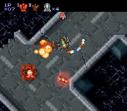
This mode really deserves its own page, there is just so much to talk about. You get one layer with 256 colors that can be stretched, skewed, and rotated. Any time you see something zoom in or out, that’s mode 7. One limitation, you get only 256 tiles max, and those individual tiles can’t be flipped. All layering effects have to be done with sprites. F-Zero has a perspective effect by zooming in as the screen gets closer to the bottom.


Contra 3.
Final Fantasy 6
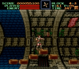
Super Castlevania 4
Super Mario Kart

.
.
.
.
Modes 2, 4, and 6 have the option to use Offset per Tile Mode (also called Offset Change Mode).
Mode 2 and 6 works like this. You put the table of offsets where layer 3 map should be (neither of these modes has a layer 3). The first part of the table affects horizontal shifting (course shifting only) and the second part of the table affects vertical shifting (fine 1 pixel shifts). You don’t have to enable layer 3 on the main screen, just layer 1 (and/or layer 2).
It should really be called Offset-Per-Column, since each value affects an entire column of the screen. There are 32 columns times 2 bytes per column is 64 bytes for horizontal offset followed by 64 bytes for vertical offset. The left most column of the screen is unaffected by offset-per-tile… it will use that layer’s usual scrolling values. So, the first entry in the OPT table affects the 2nd column, and so forth. And, the right most OPT value is for when the screen isn’t exactly aligned to a tile (horizontal scroll & 0x07 != zero) , so you can see a portion of a 33rd column on the far right. Some games use a window to hide the left most 8 pixels of the screen so it doesn’t have to manage that part, which isn’t affected by OPT.
When I first tested this mode, I thought that the OPT values in layer 3’s map correspond to layer 1’s map. But that was wrong. They correspond to the screen itself. Like, if you divide the visual picture into 32 columns. As the layer scrolls horizontally, the offset will apply to a different tile column. It is a particular column on screen that is affected, not a particular column in the map.
Just to keep things simple, we will put our offsets at the start of layer 3’s map. You probably don’t want to use horizontal offset (using map addresses 0-0x1f), so add 0x20 to the start of the layer 3 map to place your vertical offset values. The bit order works like this…
bit 15 = 0 H, 1 V (for mode 4 only)
bit 14 = BG2 affected
bit 13 = BG1 affected
10-12 = unused
0-9 = scroll offset
(lower 3 bits of horizontal offset are ignored)
So, if you wanted a vertical offset, affecting BG1+2, with an offset of 3…
111xxx00 00000011 = $e003
Really, in mode 2 or 6 you don’t really need that upper bit, so $6003
And that offset value completely overrides the vertical scroll for that column. It’s not added to the vertical scroll, but it replaces it entirely.
For Mode 4, you can’t do both horizontal and vertical OPT, you have to choose (per column) which one you want. The data will start at the beginning of layer 3’s map, just 1 set of values, and bit 15 of each value will determine if that column will offset horizontally or vertically.
You might ask yourself, will I still be able to scroll the level? Yes. Horizontally. We just need to make sure that the first 32 values in map 3 are zero, so that the “affect layer 1” and “affect layer 2” bits are off. Thus, horizontal scrolling will function as normal. (except for Mode 4, in which the first 32 values are the only values, in which case you make sure that the upper bit “H or V” is set, then OPT will only affect V, and horizontal scrolling will work as normal).
One more detail. They made it so you can have multiple OPT tables stored in the map 3 (in VRAM). Registers $2111 (BG3HOFS) and $2112 (BG3VOFS) are used to switch between the different tables. If you are doing what I said above, where the OPT values are at the start of map 3, you need $2111 and $2112 to be zero. If they are not zero, then d3-d7 of these registers will change the start location of the OPT table. These bits are the ones I mean.
00000000 11111000
and the calculation is like this. (where register $2109 defines the start of map 3)
OPT table = map 3 base address + ($2112.d3-7 * 32) + ($2111.d3-7).
Personally, I would just keep $2111 and $2112 as zero and just update the table every frame. It’s no big deal to do 32 writes per frame. You will probably want a local copy of the values anyway… so that you have something to check for collisions with objects.
.
I made some example code for Mode 2.
https://github.com/nesdoug/SNES_MODE2

.
.
Here’s a nice video covering all the modes, 0-6.
.
Another option for SNES audio is SNESMOD. It doesn’t have its own tracker, but you would use OpenMPT in the IT format, and save the file as an IT file. SNESMOD comes with a converter program called smconv.exe which can turn the IT file into a soundbank that can be used in a game. (It can, optionally, convert the IT into an SPC file to be used as a standalone music file).
https://github.com/mukunda-/snesmod
This is the original SNESMOD, and Mukunda has been nice enough to change the license to a more permissive open source (MIT). And, because of that I have gone and modified both the SPC and the SNES code. The SPC code (tree/master/driver/spc/sm_spc.asm) is supposed to be assembled with TASM using the TASM07.TAB file as the table… but I found it easier to assemble it with ca65 using blargg’s macro pack.
You can find both TASM and smconv.exe in the PVSNESLIB repository. Also the SPC code here has a bug fix that is missing from the original version.
https://github.com/alekmaul/pvsneslib/tree/master/pvsneslib/snesmod
https://github.com/alekmaul/pvsneslib/tree/master/devkitsnes/tools
(by the way, absent is the TASM documentation, which I found online. As far as I know, it is not freeware, and it asks that you pay for a license and register each computer that uses it… which is another reason that I suggest you use ca65 if you need to reassemble the SPC code). It didn’t assemble perfectly at first, but I only needed to make a few minor syntax changes to get it to work.
https://github.com/nesdoug/SNES_14_SNESMOD
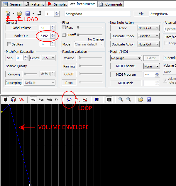
This is what you will use to make the IT files. I really thought this would be easier than SNESGSS, but surprisingly I had several difficulties. Let’s go over this really quick.
File/New IT file.
You will see 5 tabs: General, Patterns, Samples, Instruments, Comments
First thing you should do (in the General tab) is to click the button that says IT…32 channels, and set it to IT…8 channels.
Then click on the Instrument tab, and click the folder icon (import instrument) to load… and you select your .wav file. It will load it both as a sample and as an instrument. You can go back to the Sample tab if you want to turn on looping and edit the start/end point. To add more instruments, in the Instrement Tab, you will probably have to hit “Insert Instrument” first, then “Import Instrument” second, then locate the next .wav file.
Back to the Instrument tab, you will want to give it a volume envelope. So at the bottom click “Vol” and move and add dots to create a volume envelope for the instrument. If you like, you can loop the envelope, or part of the envelope. You could use this to make a tremolo effect (like a vibraphone).
An important note. If you want a sustained note, you will probably want to click the envelope LOOP button. If the LOOP button isn’t checked, and if the volume envelope doesn’t go down to zero at the end, once it reaches the last dot on the envelope, it will use the “Fade Out” value to slowly fade out the instrument. Higher = faster fade out, Lower = slower fade out. The picture below, the envelope DOES go down to zero, so there is no need for the fade out value… but if the last dot was in the middle, it would start to slowly fade out at that point.
Then you write the song in the Pattern. Select an instrument and a column and press keyboard keys to enter notes. Personally, I changed the keyboard layout to be more like Famitracker… View/Setup/Keyboard/Keyboard Mapping-Import Keys then find the More Keymaps folder and select one. I can’t remember which one I chose… maybe it was UK_IT2 (?).
This is part of where I had confusion. To play just the current pattern, you click the arrow buttons that point down below the Pattern Tab… but it will keep looping back to the same pattern. If you want to play not looped, as in to hear the whole song, you press the arrow above that (next to the word octave).
Each column is NOTE, VOL, INSTRUMENT, then EFFECT.
To add a new pattern, you right click on the next blank pattern box and select Create New Pattern.
Here are the effects that are supported by SNESMOD.
A = song speed (ticks per row)
B = set position (jump backwards to a specific pattern #)
C = pattern break (jump the the next pattern) [must be C00]
D = volume slide (fade in/out)
E = pitch bend down (for 1 line)
F = pitch bend up (for 1 line)
G = portamento speed (turns off once it hits the target note)
H = vibrato speed,depth
J = arpeggio +x semitones +y semitones
K = volume slide + vibrato
M = channel volume
N = channel volume slide
O = (I don’t think this is supported) **
P = pan slide
Q = retrigger
S = special (see below) *
T = set tempo (BPM)
V = global volume
X = set pan
*S01 – Turn off echo for channel.
S02 – Turn on echo for channel.
S03 – Turn off echo for all channels.
S04 – Turn on echo for all channels.
** The spc code sets t_sampoff, but never uses it. Makes me think it doesn’t do anything.
Oh, and to do echo settings, you have to put it in comments, like this…
[[SNESMOD]]
edl 4
efb 90
evol 70 70
efir 127 0 0 0 0 0 0 0
eon 1 2 3 4 5
edl = echo buffer size x $800 bytes, affects delay time.
efb = feedback, don’t set it too high
evol = echo volume L and R
efir = FIR filter settings
eon = which channels to have echo on.
You don’t need to use Sxx effects to turn echo on at the start of the song, it does it automatically.
I wrote a whole page about why you should use mono WAV files at sample rate 16000 and tune the samples to B+21 cents. 16000 to reduce file size without loosing too much high end. B+21 so that you can perfectly loop short samples with the BRR compression limitation of 16 samples per block. That is still my recommendation here. Use short samples if possible, there isn’t very much ARAM space and all the used samples need to fit into 64k along with the SPC code and the echo buffer.
Once the song is done, save the IT file. smconv.exe can convert it into soundbank. (It’s a command line program). -s puts it in soundbank mode (otherwise it will generate an SPC file). One interesting point here… if you specify multiple .it files, it will put them all into the same soundbank. However, it may be a waste of space since (I think) it will duplicate the samples, even if the same sample is used in multiple songs.
If you used that method, when you go to LOAD the song, you use #0 for the first song, #1 for the second. Again, I don’t think this is the best use of space. Here’s what I recommend for putting multiple songs in…
You make one song that has multiple songs back to back in it. At the end of each song you insert a Bxx effect to loop back onto itself. So each song would be a closed loop to itself. When you go to PLAY the song, you select the pattern # of the start of the song as the parameter you send when you call it. It’s a bit more of a pain to set it up this way, but (I think) you save ROM space, as samples used in multiple songs would only be stored once.
You might need many many songs, and this method won’t be enough, because you will run out of ARAM space to fit all the song data. In that case, you will need to make multiple soundbanks.
Another advantage of this (multiple songs squished together into one song) approach is that you can switch back and forth between songs without having to wait for a it to be transferred from the SNES ROM to the ARAM. You only have to wait at the beginning when you initially load everything.
When you include the soundbank to the SNES source file, it needs to be located at the very beginning of a bank. If you have multiple soundbanks, each needs to be at the beginning of a bank (ie, address $8000 in LoROM mapping).
For sound effects, you can make a separate soundbank… just an IT file with no song, just samples, converted by smconv into a soundbank. Or, you can use the existing song soundbank to store your samples, but there is a caveat. The song samples use a different table than the sfx, so you will have to load the sample, which might be a duplicate of a sample in the song… ie. you would have to copy the same sample in twice. But, I made a function (spcClone) so you don’t have to have 2 copies of the same sample to use them both in the song and as a sfx.
If you opt to use the streaming functions, you don’t need a soundbank, you need a BRR file (without the 2 byte loop address at the beginning, like you might find on BRR files at SMWcentral). The BRR file should exactly be divisible by 9. If it isn’t, then you will have to strip the 2 bytes off the beginning of the file. You can use brr_encoder.exe from brrtool to convert a WAV to BRR. There is an app called snesbrr.exe in the pvnsneslib github that probably does the same thing.
You need to allocate room for the streamed sample with spcAllocateSoundRegion. Send the size of the largest BRR you might use / 256 and round up) so that it can reserve space for it. This needs to be done before you Play the song. Don’t use spcAllocateSoundRegion while a song is playing. Interesting side note, there is no error check in the SPC code on size… if you load a lot of big files with spcLoad or spcLoadEffect, it could overflow into the echo buffer or the sound region.
But (to use the streaming functions) you also need to make an 8 byte array…
1 = pitch (1-6)
2 = pan (0-15)
3 = volume (0-15)
4-5 = length of the BRR / 9
6,7,8 = long address of the BRR sample
and pass the address of this array to spcSetSoundTable()
Then you call a play the sample with spcPlaySound, spcPlaySoundV, or spcPlaySoundEx and the sample will stream in as it plays.
So.. confession time. I removed the streaming functions from my version. I had modified the SPC code and I made it too big and the streaming code overlapped where the module loads, and it would crash if you tried to play a streamed sample. You can modify where the module loads, but that breaks the song playing code, because the song pointer table will be in the wrong location, and so I would need to modify the smconv.exe source code… etc, etc, etc. and I didn’t do that. The easiest thing was to disable streaming.
But, I believe I made the regular sfx playing functions robust enough that we don’t need it. Also, the streaming function had very limited ability to repitch the sample. Furthermore, it sometimes didn’t work right, such as for PAL systems. I didn’t really want to use the streaming much.
Let’s look at the files we need. In my project (SNES 14) in the SNESMOD folder there is a file called sm_spc.s which is the SPC program code. spc-ca65.asm is the macro pack from blargg that allows us to assemble this file with ca65. The output file is called snesmod_driver.bin and that is what we are sending with the spc boot code. I just .incbin it between these labels SNESMOD_SPC and SNESMOD_SPC_END.
Over in the MUSIC folder is smconv.exe which I used to convert the .it files into soundbanks (the .bank files). The other files generated (.asm and .inc) aren’t interesting to me.
Also in the MUSIC folder, snesmod_ca65.asm has our SNESMOD 65816 functions. I made some changes. Also, the SFX_LIB.asm has some functions for generating a sfx sequence. SFX_DATA.txt is the data for those sequences.
spcBoot – call this at the very beginning to send the SPC program over to the ARAM.
spcSetBank – tells the Loading functions where our soundbank is located. Use it before spcLoad and again before spcLoadEffect.
spcLoad – loads a song (and its samples) to the ARAM. (Also, it resets the sfx loader back to zero). The parameter is if you have multiple songs loaded to the same soundbank.
(Note, spcLoad takes a long time, maybe even several seconds to complete)
spcPlay – plays a song. The parameter is the starting pattern #.
spcStop – stops the song
spcSetModuleVolume – sets the volume for the song (0-255)
spcFadeModuleVolume – fade in or out the song volume
spcLoadEffect – loads a sfx sample (up to 16). The parameter is the position of the sample in the soundbank, which may or may not be the same as the “id”, which depends on the order that the samples are loaded as effects.
spcEffect – plays a sfx sample. The parameter is the “id”
spcProcess – call this once per frame. Several of the functions above do nothing at all until spcProcess is called. They are stored in a queue and sent to the SPC one at a time.
Functions I removed —
spcTest – didn’t seem to do anything useful
spcAllocateSoundRegion – tells the SPC how big the streamed BRR might be
spcSetSoundTable – sets pointer to an 8 byte array (see above) describing the BRR sample. You need 8 bytes per BRR sample you would use.
spcPlaySound – play the streamed sample (using that 8 byte table)
spcPlaySoundV – same, but with custom volume setting
spcPlaySoundEx – same, but you manually send it the settings (volume, pitch, pan)
spcProcess calls spcProcessStream, which needs to run every frame
Note, streamed sound always plays on channel 7.
Functions I added —
spcGlobalVolume – set the volume level for everything (except echo) (0-127)
spcEffect – has been modified so pitch can now be 0-60 which corresponds to C2 to C7.
Before, it was volume, pan, pitch, and id. Now it’s just volume, pitch, and id.
Note, I made it so that sending a volume of zero will cancel the effect.
spcFxParams – additional parameters. Call this before you use spcEffect. It is used to set the pan and which channel the effect will go to. Originally, you wouldn’t get the choice, it would alternate between channels 6 and 7.
spcClone – copy the pointer for a BRR from the song table to the sfx table. Do this after loading the song to the ARAM. This is so you can use a BRR sample from the song as a sound effect without having to have 2 copies of it. (I’m using the word clone in the sense that it is used in programming, which is that the data itself is not copied, only creating a 2nd reference to the same data.)
Functions in SFX_LIB —
Sfx_Stop_All – stops the sound effects
Sfx_Queue – use this to call a sound effect from the data tables, however only the last sfx called per frame will actually play. It’s not really a cue or stack or whatever, I just didn’t want to call the sfx functions multiple times a frame and waste so much CPU time trying to communicate with the SPC. I believe that allowing only one sfx per frame should be sufficient… however, you might decide that one sfx is more important, and you might have to modify this code so that the more important sfx has higher priority.
Sfx_Process – call this once per frame. It handles new sfx to play (from the queue) and it processes the data of
If you look at the example, in main.s, you notice that the “id” of each sound effect depends on the order that they are loaded, not the order that they are in the soundbank.
ldx #0 ;saw
jsr spcLoadEffect
ldx #1 ;square
jsr spcLoadEffect

ldx #2 ;piano
jsr spcLoadEffect
So, the 0,1,2 here refers to the sample’s position in the soundbank, and coincidentally since they are loaded in the same order their ID would be 0,1,2 as well. If you changed the order and put ldx #2 ;piano first, then the piano sample would have the “id” of zero (for when you play it with spcEffect). I threw a curveball and put…
lda #1 ;strings
jsr spcClone
and actually, that the string sample would have an “id” of #3 (because of the order of how things were loaded to the SPC). The lda #1 here refers to the position of the sample in the song’s soundbank. If you open the song IT file, this would be the 2nd sample (the first sample would be #0).
Max Sound Effects are 16.
My main goal in modifying SNESMOD was to get a sound effect note sequence. This is what I came up with. Once all the sound effects are loaded, you just call Sfx_Queue to trigger a note sequence. The data for that is store in SFX_DATA.
The data system is fairly easy. 1-127 means wait that # of frames. 0 = end of data. $80-BF = pitches of notes. $C0-CF = id of sample. $D0-DF = pan (L to R). $E0-EF = volume. $F0 = retrigger off. $FF = retrigger on. There is table of constants you can use. Unfortunately, there is no app to generate this data, you just have to type it in.
So… I should explain an important point, the volume and pan don’t go into effect until a pitch is entered (that is just the way I decided, a new pitch is the thing that makes the code send the info to the SPC) which means you would have to send the note signal again, which would restart the note. Because this might sound weird retriggering the note over and over, I made it so you can skip the retriggering part.
Don’t put “retrigger off” before the first note in the sequence. That note needs to be triggered. Also, if you volume down to zero and then have more sequence after that, you will have to retrigger the next non-zero volume part (internally, my SPC code sees a volume of zero as “off”). Retrigger means that it sends a key off and then key on signal to restart the BRR sample.
Maybe I will refactor this in the future. It’s a bit complicated, and some of the data is repetative (putting the same note value over and over). But, it seems to work the way I planned it, and I’m not having any difficulties making data.
One of the key things that I changed is that you can have LOOPED samples for sound effects. That way you could use very small BRR samples… like 128 bytes, for example. How do you loop the sample? In OpenMPT, under the sample tab, change the sample to looped, and change the start and end points of the loop. Keep in mind that the length of the sample and the staring loop point need to be exactly divisible by 16. That is a limitation of the BRR compression format.
SNESMOD has more effects column possibilities, such as arpeggio and volume slide. You can make a more elaborate volume envelope (SNESGSS uses only the built in ADSR), and can make a looped volume envelope for a tremolo effect. It is a little weird that the effects column requires you to put the same effect on every row, where other tools let you use an effect once and it persists until it is shut off.
SNESGSS gives you better information about the size of each thing and how much room you have left. Originally, SNESGSS didn’t have the ability to use echo, but I manage to fix that issue.
I still feel like both of these are acceptable, but need further development.
Note: I’ve been told the version of smconv.exe in my github may have a minor bug that incorrectly calculates the size of some things… although the data seems to be correctly playing back… I’ll assume that the bug makes it more difficult to determine how much space is available. Maybe I can fix this soon.
This is a bit off subject for my other topics, but I find this stuff fascinating. The Sega Genesis / Mega Drive has a very interesting FM synth chip, YM2612. It also has a simpler (pulse wave) audio chip, TI SN76489, which isn’t much different from earlier consoles (NES, gameboy, etc), and I won’t talk about that today. It was the FM chip really made Sega Genesis music shine.
This is for newcomers, who are not familiar with how FM synth works, and are wondering how to make their own instruments for it.
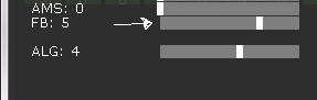
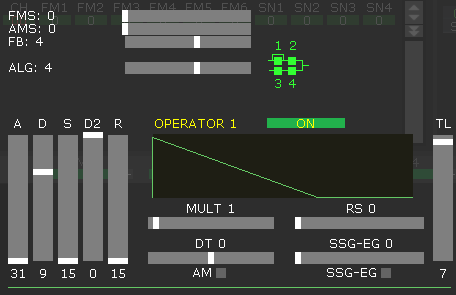
I am using Deflemask, set to Genesis. Now, if you click on the “edit” next to the instrument, you get this panel with 100 different settings and it’s not clear what everything does.

So, I’m going to try to make this as simple as possible, so you can understand it. The FM chip is generating sine waves. It generates 4 different sine waves, and their rates depend on the MULT (multiplier) values. Those sine waves could be half speed (MULT = 0), normal speed (MULT = 1), double speed (MULT = 2), or higher. It volumes up or down each sine wave based on a standard ADSR model, and then combines them based on the Algorithm (ALG).
The standard FM synthesis has a carrier wave and a modulator wave.
We start out at Algorithm 4, which has 2 separate sets of FM synth. OP 1 modulates OP 2. OP 3 modulates OP 4. Those are then combined to generate the note. Algorithm 4 is a good place to start.

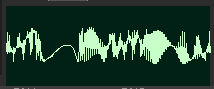
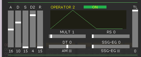
Let’s simplify it a little more, just for learning purposes. Turn off OP 1, OP 3, and OP 4 by lowering their TL (max volume) to the bottom (127 = silent). That leaves OP 2 as a unmodified sine wave. I raised the S (sustain level) so it’s just a constant tone.

Because OP 1 is off, it is unmodulated. Let’s turn OP 1 back on, by raising its TL nearly to the top. (Also, I set S, sustain level, to the top so it’s a constant value). TL is very touchy… it’s not linear, it’s some kind of logarithm scale. This is a middle range modulation.

And this is the output.

If you turn it up, while OP 1 has its TL very high, you get so much modulation it turns into noise.
This effect could be used for percussion instruments, such as cymbals.
But, the main takeaway is that OP 1 modulates OP 2, and OP 3 modulates OP 4. Other algorithms modulate in different ways, and I will talk about that later.
.
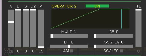
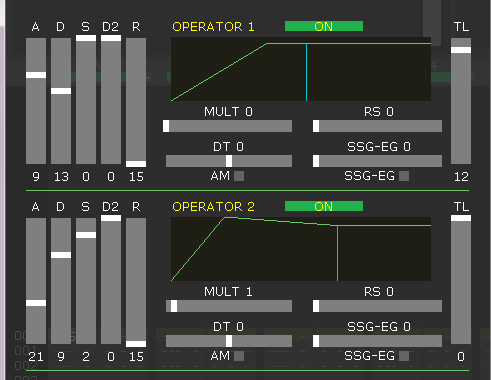
Now, let’s go over the ADSR settings.

A is the initial fade in period. It raises to the TL level, and then it immediately goes into decay until it reaches the Sustain level, then if D2 is set to the top it will hold until it gets a “note off” signal, and that’s where R (fade out) comes in. But, if D2 is set low, it will automatically fade out after it reaches the sustain level.
“Note off” is the TAB button in the pattern editor. It will say “OFF”.
The ADSR for the carrier wave (in Algorithm 4, those are OP 2 and OP 4) will change the volume of the note. If you want a fade in, you could set the values like this, and increase the attack period.
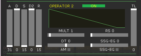
Or if you want a fade out, you lower S Sustain level and D Decay controls how fast it fades out.
and adjusted the settings until I got a similar output.
But, back on subject. ADSR… how does it affect the modulation wave? Where the value is high, there is more modulation, and when it is low the carrier wave returns to a basic sine wave.
OP 1 will be the modulator for OP 2…
You could keep the modulation wave constant, and get an unchanging tone.
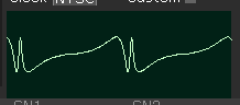
Or you could fade in to get a wah kind of effect (below)
Or, you could start at full modulation and fade it down for a “ow” sound (below)

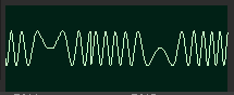
Now, I said that this chip only makes Sine waves, but if you do some things, you can kind of fake some other waveforms. If you turn just OP 2 and OP 4 on, and play them at max level with the exact same settings, they combine and the peaks will clip, and it forms square waves.
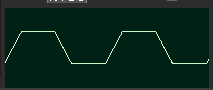
Interesting effect, but 99% of the time you would want to set the 2 carrier waves to different multipliers.
If you add feedback at just the right level, (carrier wave at MULT=1) you can kind of get sawtooth waves.

Most of the instrument design decisions will be carefully adjusting the TL level or the ADSR of the modulation wave. Even slight changes to the modulation wave will sound like a different instrument.
Lets go over the different algorithms in reverse order.

.

.

.
.

.

.

.

Now, Deflemask has dozens of FM instruments in a folder for the Genesis that you should try out, and usually you can get what you want by just slightly adjusting the TL on the modulation wave, or slightly adjusting the ADSR levels.
.
The FMS is frequency modulation, which is vibrato. The AMS is amplitude modulation, which is tremolo. You have to manually click the AM checkbox on each Operator that you want Amplitude Modulation to work. Unfortunately you can’t modify the speed of the FM or AM effects, just the depth.
RS (rate scale, or key scale) shortens the note at higher octaves. I just leave it at 0 or 1.
DT is detune. -3 to +3, and zero is normal. Presumably, you would set different carrier waves to different detuned rates to have them make a wuwuwuwuh kind of effect. This is kind of how a chorus effect works on a guitar.
SSG-EG has different effects depending on the value, some of them are retriggering the note, 5 is a fade in. I don’t really use SSG-EG. Values 2 and 6 continuously fade in and out, which I guess could be used as a slow tremolo effect.
There’s also some other weird mode that involves channel 3. In Deflemask you have to change the system mode to Genesis Ext Ch3. Something like… channel 3 can set 4 different frequencies to play, and those 4 frequencies can be any 4 notes. I’m not really sure how this works, so I won’t say any more.
.
The Genesis can also use samples. I believe that only one channel can use samples, and they tend to be low quality. I think people use them for drum samples, or a single vocal sample.
.
I plan to make a YouTube video so you can watch me adjust the instrument settings and hear how it changes. It’s on my TODO list.
.
The Konami VRC7 chip is also an FM synth. It was only used in the game Lagrange Point. It works very similar to the Sega Genesis chip, except that you always have 1 modulation wave and 1 carrier wave. This is from Famitracker.
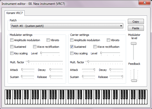
Unlike the Genesis, you mostly have to use the presets built into it. You can use any of the 15 presets and 1 custom instrument. You can’t play 2 different custom instruments at the same time. Luckily, the presets sound ok.
The ADSR values work like this…
attack (<-slow | fast->)
decay (<-slow | fast->)
sustain level (<-high | low->)
release (<-slow | fast->)
A value of zero (for A,D,or R) = don’t increase or decrease
The “wave rectification” button makes the sine wave do this.
In order to get the VRC7 set, you have to go to Module/Module Properties, and change the dropdown from “NES channels only” to “Konami VRC7”. And in order to test / hear the FM instrument while you edit it, you need to have one of the FM channels selected in the pattern editor. When you add an instrument, if you have a standard NES channel highlighted, it will add that kind of instrument. If you have an FM channel highlighted, it will add that kind of instrument.
I keep getting this question, about why I make SNES samples tuned exactly to B+21 Cents.
Let’s start with these premises:
Therefore, we must make looped samples that perfectly loop at a multiple of 16 samples. Unlooped samples (drums) can be any frequency, and need no special tuning.
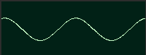
Look at the sine wave here. This is one cycle.
So we need this to exactly be a multiple of 16 samples. The shortest (highest pitch) looped sample we can make is 16 samples per cycle. 32000 samples per second / 16 samples = 2000 Hz. Which is B6+21 cents. Here’s a chart of all the possible tunings for simple, short, looped samples.
32000 / 16 sample loop = 2000 Hz = B6+21 Cents
32000 / 32 sample loop = 1000 Hz = B5+21 Cents
32000 / 48 sample loop = 666.7 Hz = E5+19 Cents
32000 / 64 sample loop = 500 Hz = B4+21 Cents
32000 / 80 sample loop = 400 Hz = G4+35 Cents
32000 / 96 sample loop = 333.3 Hz = E4+19 Cents
32000 / 112 sample loop = 285.7 Hz = D4-48 Cents
…(note, middle C would be here at 261.6 Hz)
32000 / 128 sample loop = 250 Hz = B3+21 Cents
32000 / 144 sample loop = 222.2 Hz = A3+17 Cents
32000 / 160 sample loop = 200 Hz = G3+35 Cents
32000 / 176 sample loop = 181.8 Hz = F#3-30 Cents
32000 / 192 sample loop = 166.7 Hz = E3+19 Cents
32000 / 208 sample loop = 153.8 Hz = D#3-20 Cents
32000 / 224 sample loop = 142.9 Hz = D3-47 Cents
32000 / 240 sample loop = 133.3 Hz = C3+33 Cents
32000 / 256 sample loop = 125 Hz = B2+21 Cents
Given this chart, the most common tuning found is B+21.
So, if we make a perfect loop, the wave will continue infinitely, and a short sample can play as long as you need it with no problems. But, if the loop is even a little bit off, you get weird clicks and buzz.
And it makes sense to tune ALL samples to B+21 so that they are in tune with each other. To do that, I record at C and then slow down the speed by 4.5-4.6% in Audacity. (Effect/Change Speed… Percent Change = -4.6%).
And, I’m sure some naysayer will argue that you could use a number of other tunings, if the loop was longer… say 1000-10000 samples long. Yes, you could just record at C and make a very large loop, and cross fade them, but remember premise 1 above, there is limited ARAM space. We want each sample to be as short as possible.
There might be a few exceptions. Strings (violins) don’t sound very good with a short loop. The best sounding string samples I have heard have a very long loop period… 10000+ samples. But for 99% of samples, I find it’s best to just copy the last cycle, cut to the nearest 16, and then loop that last single cycle repeatedly.
Side note, I usually resample my original samples to 16000 Hz (mono), before importing to SNESGSS. You do that in Audacity by opening the WAV at whatever rate it is. Select and copy it. Open a new file, and change the project sample rate (bottom left) to 16000, then paste the sample. This usually works best in order to reduce file size without losing too much high end. But, sometimes you need 32000 Hz if the sample has a lot of high frequency sounds (for example, cymbals).
I have made a ton of samples freely available. Check them out. You need SNESGSS to open these files, and go to instruments to hear them. You can save the instrument (to mix and match). You can extract the original WAV. Or, you can export an SPC file, and then open that with Echo4GSS (an app I made), which can extract all the BRR files.
https://github.com/nesdoug/SNES_13/tree/master/MUSIC/More_Samples
(SNESGSS is in the MUSIC folder also = snesgssQv2.exe)
https://github.com/nesdoug/Echo4GSS/releases/
Most of them were made with Famitracker or Deflemask. The drums are all royalty free samples.
Famitone 5 updated, fixed issue with Qxx/Rxx effect sometimes not working (if it was on a separate line, without a note next to it).
mmc3 example code has been updated, bug fix to stop possible conflicts with interrupts using the Bank Swap Register.
!! Half of the NES example code was updated. Mostly changed the collision code to be clearer and easier to read. But, also, the full game had some improved graphics put in.
.
I made some changes to the neslib and nesdoug library files.
There was a bug where, if you called one of the sprite functions at the exact end of the frame, it could have placed only half of a sprite’s data in the sprite buffer before the nmi sent it to the OAM RAM for the next frame. This could cause an incorrect sprite to be be shown.
The nmi code has been modified so that it will only DMA the OAM (sprite data) if you have reached the next ppu_wait_frame() or ppu_wait_nmi(). Now, a lag frame will just result in the previous frame being shown twice, with no changes.
Another change — the VRAM update code will clear the VRAM buffer each frame, automatically. You don’t need to call clear_vram_buffer() unless you are changing scenes midframe, and want to cancel some pending updates.
(Originally, I removed clear_vram_buffer() but put it back in 10/31/2022, because you might need it.)
And, I changed the name of flush_vram_update_nmi() to flush_vram_update2(). The name was misleading, the way I was using it — entirely outside of the nmi (ie. pushing updates to the PPU with the screen off).
One caution — split screens still can’t handle lag frames. If you are using a sprite zero split screen, make sure that the code isn’t so complex that it runs past the bottom of the frame. I suppose you could rewrite the nmi code (in assembly) and put the split screen code directly there, to fix it.
I did make sure that the MMC3 code can handle lag frames and do split screens. That is because you can handle the split with IRQs. The nmi code still runs the IRQ function on lag frames.
Minor change — I redid the Full BG and Fade examples. The code is the same, but I thought I could make it look nicer if I used the NESIFIER tool that I made.
old was

new is

.
More changes, October 2022.
Bug fixes in the MMC1 example code. A poorly timed bank change during NMI could crash the game, and that was fixed. Also, the final bank pop wasn’t putting the default bank in. That was fixed (and also in the MMC3 code example).
Jan 2023
SPEZ (SNES sprite editor) has been updated.
M1TE and M8TE have been updated / improved.
NESIFIER (converts an image to NES format) has been updated to 2.2.
