There are so many topics to discuss. It would be very difficult to cover 100%. Let’s briefly mention a few of the things I forgot to mention.
Multiplication and Division
SNES has hardware to perform multiplication and division. Actually, it has 2 ways to do multiplication. You can look at my EasySNES code to find examples of these (link below, search for multiply: and divide:). They are a little slow, so you can’t expect to do this 100x a frame. You have to wait a several cycles before you get a result for the regular multipy and divide functions (see the NOP opcodes, which do nothing but wait).
If you aren’t using Mode 7, there is a second multiply function (signed) which is much faster. I need to rewrite that function (TODO). But the regular Multiply function works fine.
Well, this one is over $200 US, but the basic model is less than $100, and it is well worth it. It works great. It uses a MicroSD card to hold the game ROMs.
Mode 7
This is the big enchilada, but I haven’t quite figured out this mode. Especially, setting up a tool chain for editing. Mode 7 can stretch and zoom and rotate. Many of the coolest SNES games use this in some way. It’s just currently above my skill level.
I do plan to work on this in the future. I wrote a tool called M8TE which can import an image to Mode 7 and create mode 7 maps.
IRQ Timers
This is for timing mid screen events. You should try to use HDMA instead. If all 8 HDMA channels are being used, you could do a 9th thing with IRQ timers.
You need to enable IRQ timers (probably just the V timer). and CLI to enable IRQs on the CPU. And you need to add code to the IRQ handler. Once set, the counter will trigger an IRQ signal once the PPU reaches a specific scanline. H counter would fire an IRQ signal every scanline, and you probably don’t want that.
Enhancement Chips
Another thing that is a bit over my head. The SA-1 chip is just a much faster 65816 chip, and that might be the easiest to use.
enemy AI functions (probably wouldn’t be useful to you)
.
The cool chip is the SuperFX chip (GSU). That’s what StarFox used. It would be nice if I could figure it out, and explain it. But, I can not.
Other Modes
Hi resolution. Modes 5 and 6 are double horizontal resolution. They can also, optionally, do an interlaced mode which doubles vertical resolution. Very few games used hi resolution.
Offset per tile Modes 2 and 4. I need to investigate these a bit more. I don’t want to put incorrect information here.
SRAM
For LoROM, SRAM is mapped to banks $70–$7D in the $0000-$7FFF addresses. And also in the $FE-$FF banks in the $0000-$7FFF addresses. (7e and 7f banks are the WRAM, so that couldn’t be used for SRAM). That gives a total possible 512kB SRAM (battery backed save RAM).
You will also need to indicate in the header that the ROM is using SRAM. I think that’s mapped to $FFD7, but it’s this line in the header.asm file
.byte $00 ; backup RAM size
The value is (2^# in kB). 3 is 8kB, 4 is 16kB, 5 is 32kB, 6 is 64kB, 7 is 128 kB, 8 is 256kB, and 9 is 512kB. 0 means 0kB.
Oh, and the previous line, mapped to $FFD6, should have the d1 bit (0000 0010) set. To indicate a battery for the SRAM.
Once you have correctly set this, the emulator should automatically be creating SRAM save files, that persist after power off. You can freely read and write to this anytime, and you can save your game by keeping the progress stored in the SRAM.
What is color math? If you’ve ever worked with Photoshop, it would be like blending 2 different layers with the settings on Add or Subtract. In this case the layers are the MAIN screen and the SUB screen. Everything we have done so far deals with the MAIN screen. So let me try to explain the SUB screen.
All that stuff that the SNES does to produce a picture, putting layers on top of each other, tile priorities, sprite priorities, etc… it does all that TWICE. If you set the settings for the MAIN screen exactly the same as the settings for the SUB screen, it would produce the exact same picture TWICE… with 1 difference. The main screen uses color index zero as the backdrop color (any pixel that is transparent), and the sub screen uses the “fixed color” as the backdrop color (register $2132).
You would never see the SUB screen, unless you turned on the color math registers, which would then blend the 2 pictures together, using either addition or subtraction. And then there is an optional halving step after that. Each pixel on the screen, the R values are added or subtracted, and the G value, then the B value. That value is clamped to the max and min without overflow. (each RBG value is 0-31)
Let’s say we have it set to ADD. And the main screen pixel is gray 15,15,15, and the sub screen pixel is dark red 10,0,0. The final pixel would be 25,15,15.
If we added the HALF option, each value would shift right once (rounding down), giving a final pixel of 12,7,7.
If we set the color math to SUBTRACT (no halving), the final pixel would be 5,15,15. The RGB values of the sub screen are subtracted from the RBG values on the main screen.
If we added the HALF option, each value would shift right once (rounding down), giving a final pixel of 2,7,7.
Note, any pixel in the sub screen that is transparent will not be halved.
The main use for Color Math is for transparency effects. You will want Adding and Halving. That would equally blend the main and sub screen.
The least useful setting is the subtract and halving. That would just produce a very dark picture, and almost no games used this.
.
There is a completely different kind of color math operation, that uses ONLY the fixed color. That color is applied to the entire MAIN screen, and if halving is set, it will work for the whole screen. If you set the fixed color register to green, and had the color math set to ADD, it would add a green tint to the screen.
The fixed color register $2132 is weird. The wiki example suggest writing each color separately to it (3 writes for R,B, and G). However, you could set them all to a specific value with 1 write. Such as LDA #$E0, STA $2132 would set all fixed colors to zero.
Before we dive into the code, here’s a video. You can probably skip most of this video, which goes into too many details about how the 2 different screens are generated.
Example ROM
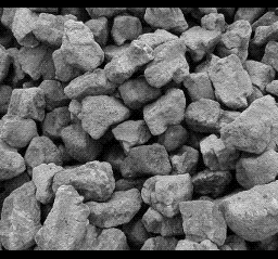
I put BG1 on the main screen (gray rocks) and BG2 on the sub screen (color bars).
No effect. Color Math disabled.
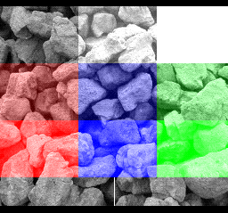
Just the Sub screen. (seen by setting the “clipping always to black” bits in the color math logic, and adding the sub screen).
Note, the top left is black (non-zero index). The bottom left is zero index (transparent). The sub screen will show the “fixed color” (register 2132) where there is transparent. Right now the fixed color is black. Color halving will not work for a transparent pixel on the sub screen. If you notice, the bottom left square will not change at all for these examples, even when halving is indicated.
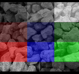
Color Math Adding.
Color Math Adding and Halving.
Color Math Subtracting.
Color Math Subtracting and Halving.
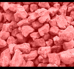
Fixed color only (red at 50%), Color Math Adding.
Example Code
$2130
ccmm--sd
cc = main screen black if... *
--mm---- = prevent color math if... *
------0- = fixed color
------1- = sub screen
d is for an unrelated thing

* 00 => Never
  01 => Outside Color Window only
  10 => Inside Color Window only
  11 => Always

$2131
shbo4321
0------- add
1------- subtract
-0------ normal
-1------ result is halved
b = backdrop, o = sprites, 4321 = layers enabled for color math

$2132 (fixed color)
bgrccccc
b/g/r = Which color plane(s) to set the intensity for.
ccccc = Color intensity.
So let’s go over each examples.
1- no effect, turn off color math
lda #$30 ; = off
sta CGWSEL ; $2130
;and make sure fixed color is black
lda #$e0 ; RGB, value = 0
sta COLDATA ; $2132
2- adding
lda #$02 ; color math with subscreen
sta CGWSEL ; $2130

;adding, not half, affect all layers
lda #$3f
sta CGADSUB ; $2131
3- adding and half, same as last one, just add one bit to the 2131 write
;adding, half, affect all layers
lda #$7f
sta CGADSUB ; $2131
4- subtracting
lda #$02 ; color math with subscreen
sta CGWSEL ; $2130

;subtracting, not half, affect all layers
lda #$bf
sta CGADSUB ; $2131
5- subtracting and half. Same as last one, but add one bit to the 2131 write
;subtract, half, affect all layers
lda #$ff
sta CGADSUB ; $2131
6- fixed color only
;turn on color math, fixed color mode
lda #$00
sta CGWSEL ; $2130

;adding, not half, affect all layers
lda #$3f
sta CGADSUB ; $2131

;set the fixed color to red 50%
lda #$2f ;red at 50%
sta COLDATA ; $2132
We could have also set half mode.
7- see just the sub screen. We did this by setting the “always clip main screen to black” bits in 2130, and then adding the sub screen to the now completely black main screen.
lda #$c2 ;= clip main always to black
sta CGWSEL ; $2130

;adding, not half, affect all layers
lda #$3f
sta CGADSUB ; $2131
Other examples
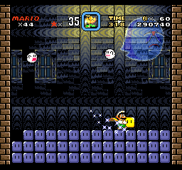
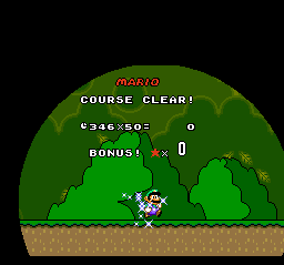
Color math only affects some sprites. Only sprites that use palettes 4-7 are affected by color math. That is why Mario (and the little ghosts) are solid.
Windowing can affect where the color math applies. With HDMA adjusting the window, you can make some cool effects.
Tint the whole screen (adding a fixed color)… actually, upon further investigation, this is subtracting, which makes the screen slightly darker than the original. Also, the COLOR MATH is not in fixed color mode, it’s in subscreen mode, but NOTHING is enabled on the subscreen, so the subscreen is filled with the backdrop color (which for the sub screen is the fixed color). I guess that works too.
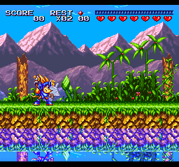
Smooth Transparencies (add and halving). This is the most common transparency effect on the SNES.
Sparkster, the water.
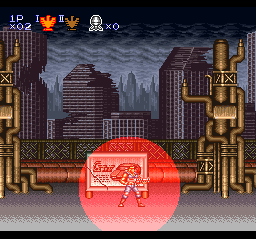
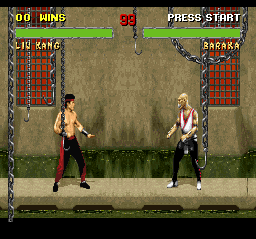
And creating shadows (subtracting) Mortal Kombat II. It’s hard to tell, but their shadows are created by color math subtraction. You could also give the appearance of clouds moving overhead by subtracting a cloud shape and having it scroll.
HDMA is a way to write to PPU registers while the screen is drawing. You can change values at specific scanlines, to create unique effects.
The H is for H-Blank. Remember before, when we talked about V-blank (vertical blank), where the PPU isn’t doing anything for a short while after drawing each screen? Well, it also pauses a VERY SHORT time after drawing each horizontal line. Just long enough for the 8 HDMA channels to quickly change a register or send data, before the screen goes to write the next line.
They work in order, 1,2,3,4,5,6,7,8. They can all write 1 thing (1,2 or 4 bytes) per line. Or you can set them to wait a specific number of lines before changing a value.
HDMA uses the same registers as the DMA registers, and you shouldn’t use both at the same time. You should write zero to HDMA enable ($420c) before performing a DMA. Because the oldest revision of the SNES has a bug where it can crash if they both happen at the same time. Or, just make sure they aren’t used at the same time.
Here’s an interesting video on DMA and HDMA.
Examples
Here’s some things you can do with HDMA.
Changing the BG color with HDMA, to create a color gradient.
Changing the Window (there are 2 windows) with HDMA, to block off portions of the screen. The windows have left and right registers, which need to be written every scanline to create these shapes.
Mode 7 parameters. (lots of registers to change hundreds of times a frame).
4301 – the PPU destination register. 21xx. So if you write $22 here, the HDMA will write to the $2122, the CGRAM Data Register.
4302-4 – the address of the HDMA table. 2=low, 3=middle, 4=upper/bank #.
4307 – if using Indirect HDMA, this is the bank # of the Indirect Addresses.
Anything marked “no”, don’t touch them. They are used by the HDMA hardware.
Then you write the channel (bitfield, each bit represents a channel, 1 for ch0, 2 for ch1, 4 for ch2, 8 for ch3, etc) to $420c, the HDMA enable register. Presumably, you would do this step during v-blank or during forced blank. I think it will misbehave for 1 frame if you turn HDMA on mid-frame.
.
OK, so we are pointing the HDMA registers to a table (byte array). For a direct mode, the table would be a scanline count, then (depending on the TTT mode) 1,2, or 4 bytes to be written. Then another scanline count, then more bytes. Scanline count, bytes. Scanline count, bytes. Etc, until it sees a zero in the scanline count slot. From my own examples…
That reads 32 lines, value $0f. 32 lines, value $1f. 32 lines… etc down to the terminating 0. One interesting thing is that the $0f is written immediately at the very top of the screen. THEN it waits 32 lines.
Here’s another example, when the transfer mode is “1 register write twice”.
10 is the scanline count. Then 2 bytes to write. Then 10 scanline count. Then 2 bytes. Etc.
Indirect Mode
43×0 register, we can set it to Indirect. Only with indirect do you need to write to 43×7, the bank of the indirect address. The table will always be sets of 3s. First the scanline count, then an indirect address (ie. pointer) to where our data is. I wrote the HDMA table like this…
The .addr directive outputs a 16 bit value, low byte then high byte. I think you could have also used the .word directive. So, 8 is the scanline count, then an indirect address. Our bank byte is $7e, so the first one points to WRAM $7e1000. The second one points to $7e1002. Etc.
One of the advantages of the indirect system is that you can have a repeated pattern that changes.
I had copied the Indirect Table to $7e1000. It looks like this.
All of these are values to be written with HDMA to a PPU register. In this case, a horizontal scroll register, which is write twice (low then high bytes).
This is example 3. I am also shuffling these values every 4 frames, which causes the movement of the the sine wave.
Example Code
No effect. HDMA is turned off by writing zero to $420c.
.
.
Example 1. Changing the BG color.
I’m actually setting up 2 separate HDMA transfers. First to set the CG address to zero. Second to write 2 bytes to change the #0 color. You have to rewrite the address each time, because it auto-increments when writing a color.
stz $4300 ;1 register, write once
lda #$21 ; CGRAM Address
sta $4301 ;destination
ldx #.loword(H_TABLE1)
stx $4302 ;address
lda #^H_TABLE1
sta $4304 ;address

lda #2
sta $4310 ;1 register, write twice
lda #$22 ; CGRAM DATA
sta $4311 ;destination
ldx #.loword(H_TABLE2)
stx $4312 ;address
lda #^H_TABLE2
sta $4314 ;address

lda #3 ;channels 1 and 2
sta HDMAEN ;$420c
And we have 2 HDMA tables (see the example code). Each time we are waiting 10 scanlines between changes. Each time, adding a little more red.
.
.
Example 2. Changing window 1 left and right positions.
A window punches a hole in one or more layer. There are 2 windows, but we only need 1 for this example. The only parameters you can set are left and right (and inverse, and combinations with the other window). But with HDMA, you can adjust the window parameters as the screen draws, and draw a shape. Circle shapes are very popular.
If the left position is > than the right position, the window will not appear. That is what we are doing for the top and the bottom of the screen. You also have to tell it which layers are affected with the $212e (window for main screen) and with the $2123-5 registers.
I’m using 2 HDMA channels, and writing 1 byte to 1 register. To 2126 and 2127.
lda #1 ;windows active on layer 1 on main screen
sta TMW ;$212e
lda #2 ;window 1 active on layer 1
sta W12SEL ;$2123

stz $4300 ;1 register, write once
lda #$26 ;2126 WH0
sta $4301 ;destination
ldx #.loword(H_TABLE3)
stx $4302 ;address
lda #^H_TABLE3
sta $4304 ;address


stz $4310 ;1 register, write once
lda #$27 ;2127 WH1
sta $4311 ;destination
ldx #.loword(H_TABLE4)
stx $4312 ;address
lda #^H_TABLE4
sta $4314 ;address

lda #3 ;channels 1 and 2
sta HDMAEN ;$420c
(This could have been done with 1 channel with a 2 register transfer mode).
Note… If the scanline count is >128 (not including 128), it signals a series of single scanline writes. You can omit the scanline count for a number of lines (ie. subtract 128 from the scanline count number).
.byte 60, $ff ;first we wait 60 scanlines
.byte $c0 ;192-128 = 64 lines of single entries
.byte $7f ;1st write value
.byte $7e ;2nd write value
.byte $7d ;3rd write value
.byte $7c ;4th write value
...etc...64 lines.
.byte 0 ;end
It waits 1 scanline between each write.
Each line, I am moving the left position and right position further apart, and then closer together, which forms a diamond shape.
.
.
Example 3. Changing BG1 horizontal scrolling position.
This was already discussed above, in the Indirect Mode section. We are using a sine wave pattern to create a wave in the picture, writing twice to 1 register, the horizontal scroll of BG1.
I wanted to include at least 1 example of indirect mode. I copied the value table to the RAM, so I was able to change the values to make the pattern move. See the Shuffle_f3 function in the HMDA3.asm file. The table of Indirect Addresses points to the RAM where our actual values are stored.
This example would have been even nicer if we wrote new values every scanline. Currently, we are only changing values every 8 scanlines (to make the table simpler / smaller). Maybe even every 2 scanlines would have been enough.
lda #$42 ;indirect mode = the 0100 0000 bit ($40)
sta $4300 ;1 register, write twice
lda #$0d ;BG1HOFS horizontal scroll bg1
sta $4301 ;destination
ldx #.loword(H_TABLE5)
stx $4302 ;address
lda #^H_TABLE5
sta $4304 ;address
lda #$7e
sta $4307 ;indirect address bank

lda #1 ;channel 1
sta HDMAEN ;$420c
.
.
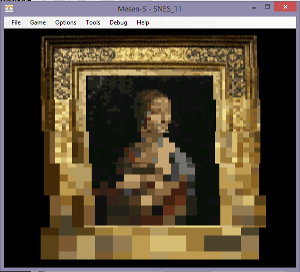
Example 4. Changing the Mosaic filter.
This is the simplest example. A single write to a single register. I haven’t discussed the Mosaic filter before, $2106 . The upper nibble is the mosaic amount (0 = normal, 1 = 2×2, etc up to $f = 16×16), and the lower nibble says which layers are affected. Sprites are never affected.
stz $4300 ;1 register, write once
lda #$06 ;mosaic
sta $4301 ;destination
ldx #.loword(H_TABLE6)
stx $4302 ;address
lda #^H_TABLE6
sta $4304 ;address

lda #1 ;channel 1
sta HDMAEN ;$420c
It waits 32 lines before increasing the mosaic value. There are bigger squares at the bottom. You probably wouldn’t use this exact HDMA effect in a game, but it is just an example of what is possible. You can change so many settings, even the BG mode $2105, which layers are active, change the location of a tilemap or tileset. I think you can even write new data to the VRAM (a little bit at a time).
.
.
Example 5. Windows with Color Math.
(the next example page will talk more about Color Math registers)
Some of the coolest effects were done with this combination. We are adding a fixed color to tint the picture, and using the windows to shape the color box. If we made the HDMA table for the window more elaborate, it could be a circle, or any simple shape. We could change the table and make it grow or squish. The windows work the same as before, but we just needed to change the settings so that the window affects color math and nothing else.
lda #$20 ;Window 1 active for color, not inverted
sta $2125 ;WOBJSEL - window mask for obj and color
lda #$10 ;prevent outside color window, clip never,
;add fixed color (not subscreen)
sta $2130 ;CGWSEL - color addition select
lda #$3f ;color math on all things, add, not half
sta $2131 ;CGADSUB - color math designation
We are setting the color math to use only the fixed color, and not the subscreen. So, we need to set the color of the fixed color register $2132.
lda #$8f ;blue at 50%
sta $2132 ;COLDATA set the fixed color
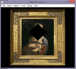
This register (fixed color) is a bit complicated, I will explain it more on the next page, but the upper bits are the color selectors, and the lower 5 bits are for value. 8 is blue and $0f is for 15 (out of 31), or just above 50%. With color math addition (with the fixed color) turned on, it would color the entire screen blue. But, our HMDA window blocks out the effect for the top, sides, and bottom of the screen, leaving a blue box in the size/shape of the painting.
.
.
Here’s a YouTube video of these examples (video is old, doesn’t include the 5th effect)
.
IMPORTANT NOTE – the top most scanline is never drawn. It’s blank. At the end of that 0th scanline, it sends the first value of the HDMA tables, and then it sets the scanline count. The HDMA table looks like the scanline count is before the value to send, but it does it the opposite… it sends the value and then it waits. That means that the first value effects the very top of the visible screen.
The HDMA table resets at the end of v-blank. Automatically. Even if it didn’t complete the table because it was longer than the number of scanlines on screen, it jumps back to the 0th item on the HDMA table, and continues the next frame from the top of the table.
Also, a count of zero terminates the HMDA for the rest of the frame, but it still resets again, at the top of the next frame, and keeps going. If there is a value listed after the zero, it isn’t sent.
This is a lesson on using SNESGSS to make SNES music.
Before you read this… I have made improvements to SNESGSS, the newest version has a Q at the end, and it has a different music.asm file. See this link for more info.
NOTE – If SNESGSS editor stops playing the music correctly (silences some or all the notes), the issue is that there is too many things loaded to fit in the ARAM. This could happen unexpectedly, because adding to the song editor might overflow the available RAM, without warning. Click over to INFO and it will probably say there is no memory left. You will have to shorten the song or remove unused samples.
Here’s an interesting video on the SPC700 and SNES audio.
Today, we are going to talk about SNES music. The APU (Sony SPC700) is a different chip entirely, and has its own 64k of RAM. At the beginning of our program, we need to load the APU with our SPC file. It is an audio program that runs automatically.
The APU is connected to an 8 channel DSP (digital sound processor). The song will direct the DSP to play different sound samples at different rates to make tones. If you are familiar with MIDI, it is similar. The samples can be looped or not. The samples are compressed into a native compression called BRR (bit rate reduction).
BRR samples are very large, and you will probably be only able to fit 10-15 samples. Each will have to be edited (perhaps with Audacity) to less than a second each, and at a reduced sample rate. We are going to work with SNESGSS (written by Shiru).
I originally found it here (you might want to look here to get the sample intruments), but don’t use this .exe because it has a bug.
and also grab the music.asm file. You will need it.
.
SNESGSS prefers to have 16-bit MONO WAV samples at sample rate 32000 or 16000. I have tried 8000, but usually the sound quality is too bad at 8000. 8000 might be ok for a bass sample.
There seems to be a bug in Audacity, when you resample to another rate (Tracks/Resample), it doesn’t actually change the project sample rate, nor will it save the project at that sample rate. What you need to do is Open the WAV file in Audacity, Select All and COPY it. Then Open a NEW PROJECT, and change the project’s sample rate (at the bottom left) to 16000. Then PASTE it. Now it will save at the correct sample rate.
Recording at the desired rate has no problems. 16000 seems to be a nice sweet spot on audio quality and file size.
SNESGSS also suggests tuning the samples to B +21 cents. I did not. I left all my samples at C. They are not in tune with the samples provided with SNESGSS, which I did not use. I think those are tuned to B +21. The reason behind the unusual tuning is to make it easier to make looped samples without clicks. BRR format is forced to be blocks of 16 samples, so a multiple of 16 samples (such as 256 samples per wave cycle) at a sample rate of 32000 (or 16000) samples per second works out to B +21.
But, feel free to use whatever tuning is easiest for you.
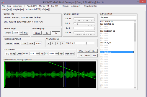
Hit the WAV button near the middle of the screen to load your samples. Setting the envelopes similar to this sounds good to me (15, 1, 7, 16). If you managed to loop the sample perfectly, you may prefer to leave the last envelope setting (SR) at 0, for a tone that can continue infinitely.
You can press the 2x or 4x buttons if you run out of room for files, to downsample by half.
To loop, click the “On” button and type in the loop start (FROM) and loop end (TO) numbers. Note – BRR sample length needs to be a multiple of 16, and the loop start and end points need to be a multiple of 16. SNESGSS doesn’t tell you that… you will probably have to use a calculator to calculate a multiple of 16 and type exact numbers in.
I wouldn’t mess with the volume or EQ settings. That is something you should have done in Audacity while editing. Just keep in mind that the SNES tends to weaken the upper range and make bright sounds feel dull. You might have to do a treble boost for the lead instruments.
This tracker will convert our samples to BRR, but not until your final export. Unfortunately, you can’t import BRR samples to it from other sources. And you can’t export BRR samples, although you could export an SPC and use spc_decoder.exe from BRRtools to extract the BRR samples from the SPC.
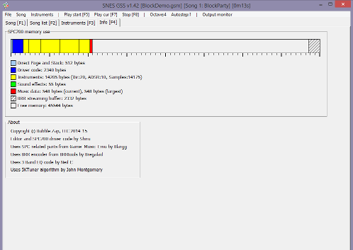
Here you can check the size of all the files. Obviously, you can’t have a bigger SPC file than 64k, the size of the APU RAM.
I should note, that we only load 1 song in the APU RAM at a time. Staring a new song will load a new song (over the previous song), so that only one song is loaded at any time. That should give you a little flexibility on overall size.
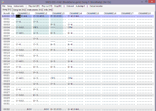
Here is the main editor. You type Z-M keys for lower octave, Q-P keys for upper octave. You can change the octave by pressing the octave button. So, this is a standard tracker, it goes downward as the song plays.
You can toggle channels on and off by clicking on the word “channel 1”, etc. You can divide things into sections. Press the spacebar to mark the end of a section. Then you can repeat the previous section with an R00 command.
The order of things is Note, Instrument, Volume 0-99, and Special effects. The SP column is for song speed (smaller is faster). You can scroll up and down with PgUp and PgDn keys, and also Home and End goes to the next section.
CTRL+End marks the end of the song, and CTRL+Home marks the loop back point.
You can import Famitracker and MIDI files (notes only), but I haven’t tried.
On this page, you can mark a song as a “Sound effect”.
Once the songs are done, you File/Export. And that will produce several files.
spc700.bin is our main SPC file. It holds the program and the samples and the sound effects data.
music_1.bin (one file per song) is the song data.
sounds.asm and sounds.h we don’t need. Don’t include them. This was for a different assembler / C compiler. You might want to look at it to find the value of each sound effect.
.define SFX_DING 0
…tells us that the DING sound effect is called with the value zero.
I changed the asm code in mid 2021, make sure you have the latest music.asm so it can handle SPC files larger than 32k. Here’s how we can include the file accross 2 different LoROM banks.
(ca65/ld65 linker specific commands).
If the SPC file is larger than 32k, you can add arguments to the .incbin command to split the file.
.incbin “MUSIC/spc700.bin”, 0, 32768
and
.incbin “MUSIC/spc700.bin”, 32768
The top one says copy 32768 bytes starting at 0. The second one (with 1 number) says to include from 32768 to the end of the file. The newest version of SPC_Init can copy the entire thing to the SPC RAM (even across multiple banks).
.
CODE
Let’s go over the music.asm file, which you should have grabbed from one of my example folders. I had to modify the original code to work with ca65.
SPC_Init – should be called at the start of the game, with interrupts off (NMI, IRQ, controllers). With AXY16 you load A with the address of the of SPC file (spc700.bin) and X with the bank of the SPC file, and JSL to SPC_Init.
By the way, running this function takes a long time. It could take 2 seconds or more.
SPC_Load_Data is an internal function, for loading data to the APU RAM.
SPC_Play_Song loads a song (data) to the APU RAM and then starts playing it. This also should be done with interrupts off. Note that this system only loads one song at a time to the APU RAM. If you have a song in and then load another song, it overwrites the first song.
With AXY16 load A with the address of the song data (like music_1.bin) and load X with the bank of the song, then JSL to SPC_Play_Song. Once it’s done, it will begin playing the song automatically.
SPC_Command_ASM is an internal function. It’s what sends signals to the APU.
SPC_Stereo is to set mono (default) or stereo audio. Load A (8 or 16) with 0 for mono, 1 for stereo. Audio channels can be panned left or right.
SPC_Global_Volume is to set the max volume, 0-127. It can also be used to fade in or fade out. One of the variables is called speed, and it is the step value, to go from previous volume to the new volume. 255 is the default speed, which is instant change (any value >= 127 would be instant). Speed of 7 seems nice for a fade, and will take 2 seconds to transition. Don’t give it a speed of zero, the volume won’t change.
AXY8 or AXY16, load A with the speed of volume change (1-255), and load X with the new volume (0-127), then JSL SPC_Global_Volume.
The SNES has a master volume variable, which affects all channels. That’s what this sets, and doesn’t affect individual channel volumes.
SPC_Channel_Volume sets the max volume for an individual audio channel. AXY8 or AXY16, load A with the channels and load X with the volume (0-127) and the JSL to SPC_Channel_Volume. I’m not sure what circumstances I would use this. Maybe to silence or dim a lead instrument, for a change in dramatic tone.
Note, the channel here is a bitfield, with each bit representing a channel.
For example, LDA #$42 (0100 0010) would effect channels 2 and 7.
Music_Stop stops the song. JSL here.
Music_Pause will pause and unpause the song (and not effect the sound effects that are playing). Load A (8 or 16) with 1 for pause and 0 for unpause, then JSL here.
Sound_Stop_All stops all sounds, song and sound effects. JSL here.
SFX_Play_Center plays a sound effect, pan center. With AXY8 or AXY16, load A with the # of the sound effect, load X with the max volume of the sound effect (0-127), and load Y with the channel (0-7), the sound effect should play. Channel needs to be higher than the max channel for the song playing. Therefore, you must reserve some empty channels in the song, if you want sound effects to play with it.
SFX_Play_Left, is the same, but pan left.
SFX_Play_Right, is the same, but pan right.
SFX_Play is an internal function that the 3 above functions call.
Streaming has been removed. See the 13th SNES example page for echo functions.
;copy the music code and samples to the Audio RAM
AXY16
lda #.loword(music_code)
ldx #^music_code
jsl SPC_Init

;turn on stereo sound
AXY16
lda #$0001
jsl SPC_Stereo
By the way “.loword()” gets a 16 bit value from a 24 bit label. ^ gets the bank of a label.
.
Now I just need to set up a trigger for the sound effect. We already have that yellow block triggering the screen to go dark, so I just snuck in a little more code there. I didn’t want it re-starting the same sound effect over and over and over each frame, so I added a variable to remember the LAST FRAME, if we were over the yellow block, and skip a trigger in that case.
cmp bright_var2 ;compare to last frame
beq Past_Yellow ;skip if last frame is true

AXY8
lda #0 ;= ding
ldx #127 ;= volume
ldy #6 ; = channel
jsl SFX_Play_Center
Our song plays from channels 1-4 (ie. 0-3), and our sound effect uses 2 channels, so we could have set this to 4,5, or 6. This function is zero based index, ie. values 0-7. So 6 means it will play on channels 7 and 8. Sorry for flip flopping between zero based and one based numbers. Hope this isn’t too confusing.
However, if we loaded X with 0,1,2, or 3. It would not play. If we loaded X with 7, only the first channel of the sound effect would play.
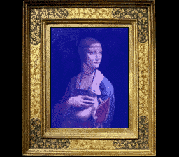
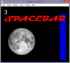
Here’s a picture of the demo again. It looks the same as the previous example.
There are other programs for getting music onto a Super Nintendo.
You could use SNESMOD with OpenMPT. I still need to research this more before I can recommend it. I have heard that a version of SNESMOD by AugustusBlackheart and KungFuFurby is good. Sorry I can’t be more informative here.
Another program, BRRTools, can convert audio files to BRR. I haven’t used it, but the SNESGSS tool uses the same code. It says you can turn BRR samples into WAV and WAV into BRR. This could be a way to use existing BRR samples in our SNESGSS projects (by using this tool to convert them into WAV files first).
Update 2023. After some test, the SNES goes through the decay phase of ADSR much faster than I expected. (much faster than the SNESGSS envelope graph shows). With SL=7, it skips it entirely. SL=6 is still nearly instant. See the results of my own testing.
I made this with SPEZ version 2. Although SPEZ version 3 is out, it has different sprite code (see example in the SPEZ folder).
This time we are going to make a collision map, and make a sprite collide with the background. The actual graphics are not that important.
I took some pictures of some blocks (and a sketch of a cube with eyes) and resized them in GIMP to 16×16 sized blocks. Then I imported everything into my M1TE tool. From there I made a 3 metatiles, green, red, and yellow. Red will be the collision blocks (1 = wall). This is what it looks like in M1TE.
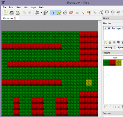
You can save the map screen as a image (File/Export Image). That was then loaded into Tiled Map Editor as the tileset.
Tiled Map Editor is a free game design tool. The entire purpose of this is to export a .csv file of our collision map… which is that collision array I was talking about.
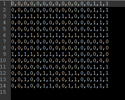
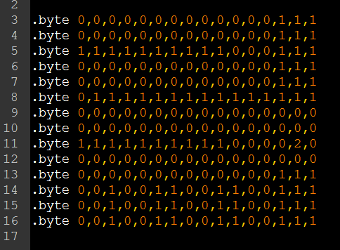
The CSV file exported from Tiled.
I added some .byte directives so it can be loaded as a byte array into the asm code. 0 is blank, 1 is red wall, 2 is the yellow square. Now we can .include it into our ASM file.
But how did I draw the map? Back when I was programming NES games, I had a whole metatile system worked out. I am doing a similar thing here, but I manually typed out each tile needed to construct a block. In metatiles.asm.
And in main, it does a loop, converting each byte of the collision map (HIT_MAP) into 4 screen tiles. And copying them one by one to the VRAM on the map. The key thing is that we again use the HIT_MAP to stop movements of the sprite.
Our code calculates where our guy is on the map, and if we are over a 1, cancel the movement. That makes him collide with the red walls.
How does it do that? Let’s go over the code. So our byte array has each block 16×16. We need to divide x and y pixel coordinates by 16 (the same as shift right 4x). But we also need to multiply the y by 16 to get to the correct row in our array, which cancels out the divide 16. So the algorithm is (Y & 0xf0) + (X >> 4). If we look at that index in the byte array, it will tell us if a point is in a wall or not. This is the code, with X and Y registers holding the X and Y coordinates…
tya
and #$f0
sta temp1
txa
lsr a
lsr a
lsr a
lsr a
ora temp1
tax
lda HIT_MAP, x
rts
I handled each direction separately. First do the X move, then see if any of the corners of our sprite are inside a wall. If yes, revert to previous X position. Then do the Y move, see if any of the corners of our sprite are inside a wall. If yes, revert to previous Y position.
This code would need to be a little more complex if we move more than 1 pixel per frame. If we are moving 2-3 pixels per frame, and the distance to the wall is 1 pixel, we should allow 1 pixel movement toward the wall… and not be stuck 1 pixel away from the wall. So, this code will need to be improved.
.
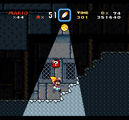
Touching the yellow square will darken the screen. We are just looking if 1 point (the middle of our guy) is over a 2 in the collision map, and changing the screen brightness variable. Remember that the $2100 register is the screen brightness. I am writing to it every frame, during v-blank. Full brightness is $0f. Half brightness is $07.
If we were scrolling in a larger world, the collision map would have to be the size of the world. You could have it compressed, and decompress it to the WRAM. You would have to keep track of X and Y movements with 2 byte variables. One thing I would not recommend is trying to read from the VRAM to see what kind of tile you are standing over. The visuals of the level should probably be separate from the collision map.
One more thing. It wouldn’t be too much trouble to turn this simple example into a platformer. You would just need to add gravity, which is adding a little bit to the Y speed every frame, and then cancelling that if your feet touch the floor. Jumping would be a sudden negative Y speed.
This is a really cool page that explains collision maps in more detail.
TODO – I need to write some code to automate generating metatile tables, or come up with some other kind of BG object system. Especially for a larger world… hand editing data tables will get very tedious.
I made this with SPEZ version 2. Although SPEZ version 3 is out, it has different sprite code (see example in the SPEZ folder).
So, this isn’t so complicated. I’m using the Example 4 backgrounds, and scrolling them with the controllers. I’m not going to go over the process of making backgrounds again. We will just talk about the scrolling code.
If you press A, B, X, or Y, you will toggle which background is selected. Visible by the sprite in the corner (1,2,3). This is the map_selected variable, which has a value 0-2.
The up/down/left/right functions will do a case switch style check on the map_selected variable. Normally, you would do CMP #1, CMP #2, CMP #3, etc. But you don’t actually need to do a CMP #0. This is something I see new 6502/65816 programmers do. The previous line “lda map_selected” already sets the z flag if map_selected is zero. Lot’s of instructions set the z (zero) and n (negative) flags. LDA, LDX, LDY, TAX, TXA, TXY, PLA, PLX, PLY, etc. If a register is loaded with zero, the z flag is set and BEQ will work.
Right_Handler:
.a16
.i16
  php
  A8
  lda map_selected
  bne @1or2
@0: ;BG1
  dec bg1_x
  bra @end
@1or2:
  cmp #1
  bne @2
@1: ;BG2
  dec bg2_x
  bra @end
@2: ;BG3
  dec bg3_x
@end:
  plp
  rts
Let’s follow this for each value. If map_selected is zero, the BNE won’t branch, it goes to the @0, dec bg1_x and then exits. If map_selected is 1, the first BNE will branch to @1or2. A is still loaded with map_selected, we compare it to #1, the BNE won’t branch, so we do @1, dec bg2_x and exit. If map_selected is 2, the first BNE branches to @1or2, cmp #1 is false, so the bne @2 branches us to th @2 dec bg3_x line.
Notice, moving the map right means decreasing the horizontal scroll variable. Moving it left means increasing it. Likewise, moving a screen down is decreasing the vertical scroll, and moving it up is increasing it.
Scrolling registers are write twice (8 bit) each. Always write twice. You can actually write to these registers any time, but we want to do it during v-blank so we don’t get any shearing of the background in the middle for 1 frame. Near the top of the game loop, we have jsr set_scroll. Let’s look at set_scroll.
lda bg1_x
sta BG1HOFS ;$210d
stz BG1HOFS
lda bg1_y
sta BG1VOFS ;$210e
stz BG1VOFS

lda bg2_x
sta BG2HOFS ;$210f
stz BG2HOFS
lda bg2_y
sta BG2VOFS ;$2110
stz BG2VOFS

lda bg3_x
sta BG3HOFS ;$2111
stz BG3HOFS
lda bg3_y
sta BG3VOFS ;$2112
stz BG3VOFS
bg1_x is a 1 byte variable, because our maps are set to 1 screen only (32×32 map and 8×8 tiles). If you made the tilemap bigger (or made the tile size larger), you would need 2 bytes for each scroll variable. With 64×32 our x needs 9 bits. If you also increase tilesize to 16×16 then we need 10 bits.
You can move each layer independently. Usually, you would have BG1 be the foreground and BG2 be the background and BG3 be either the far background or the HUD (scoreboard) always fixed in one place in the front.