Pong. Sprite collisions.

SNES programming tutorial. Example 7.

https://github.com/nesdoug/SNES_07

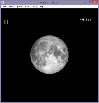
I made a simple Pong demo to show sprite collisions.

I made this with SPEZ version 2. Although SPEZ version 3 is out, it has different sprite code (see example in the SPEZ folder).

Well… I was trying to keep it simple, but I decided to use some of the more complicated code I have previously written. Copied to the library.asm file from some of the EasySNES files. OAM_Spr(copies one sprite to the buffer), OAM_Meta_Spr (copies multiple sprites to the buffer), oam_clear (clears the buffer), Map_Offset (gets an address from a specific x/y coordinate in a map). I did change the return from these functions from RTL to RTS, because all of our code is in the same bank.

I will discuss these functions further below.

Check_Collision is new. I will discuss that a bit later.

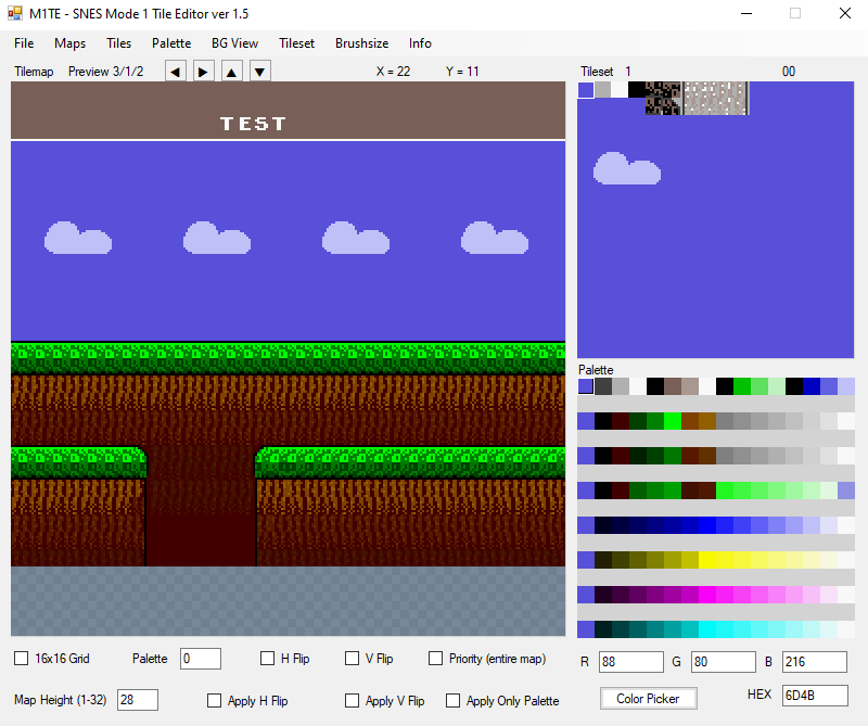
Let’s talk about the process of making this. I made a circle gradient in GIMP for the background, and converted to indexed 4 color (with dithering). Sized 256×192 (it won’t cover the entire screen).

Grad

Saved as a PNG. Imported to M1TE.

BG1

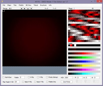
Then I drew some numbers for BG3, and filled a little on the top and bottom.

BG3

Clicked the priority checkbox for this map.

Priority

Saved all the maps and tiles and palette. Pretty much the same as previous examples of loading a background.

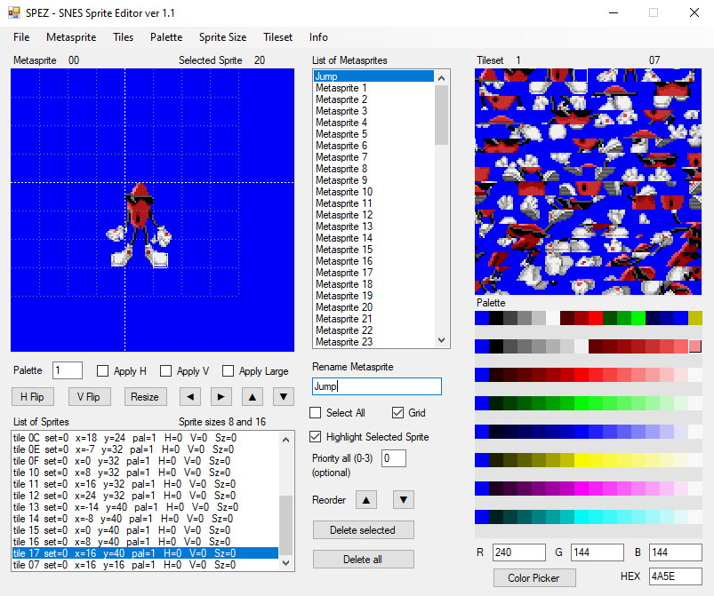
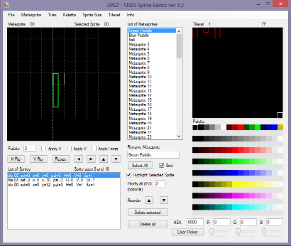
Now I opened SPEZ (my sprite editor) and drew some simple box shapes for the ball and paddle. Saved them as metasprites.asm and saved their tiles (chr) and palette.

SPEZ7

Everything is .incbin -ed in the main.asm file. We are loading everything just like the previous examples, with DMAs to the VRAM. One difference is that I wrote a macro for DMAs to the VRAM. This made the code a little easier to read and write. Let’s look at an example…

DMA_VRAM $700, Map1, $6000

This is the DMA_VRAM macro definition…

.macro DMA_VRAM length, src_addr, dst_addr
;dst is address in the VRAM
;a should be 8 bit, xy should be 16 bit
ldx #dst_addr
stx $2116 ; vram address

lda #1
sta $4300 ; transfer mode, 2 registers 1 write
; $2118 and $2119 are a pair Low/High
lda #$18 ; $2118
sta $4301 ; destination, vram data
ldx #.loword(src_addr)
stx $4302 ; source
lda #^src_addr
sta $4304 ; bank
ldx #length
stx $4305 ; length
lda #1
sta $420b ; start dma, channel 0
.endmacro

So where it says length, the macro will insert the $700 bytes (not $800, because the screen is only 224 pixels high, so I’m not filling the entire 256 pixel high map). Where it says src_addr, it replaces it with Map1. Where it says dst_addr, it replaces it with VRAM address $6000. All that code could be written in one line.

DMA_VRAM $700, Map1, $6000

Doesn’t this look nicer though? Simple. Elegant. Easy to read. Macros are your friends.

Everything between InfiniteLoop and, somewhere below that, jmp InfiniteLoop is the game loop. Every frame we wait till v-blank. Copy the OAM_BUFFER to the OAM. Print the score to the top of the screen. Read the controllers. Move the paddles if up or down are pressed.

  lda pad1
  and #KEY_UP
  beq @not_up

@up:
  A8
  lda paddle1_y
  cmp #$20 ;max up
  beq @not_up ;too far up
  bcc @not_up

  dec paddle1_y
  dec paddle1_y

  dec paddle2_y
  dec paddle2_y

@not_up:

This code is moving both paddles, because this is just example code. You could modify it, so that controller2 moves the paddle on the right. Copy this whole thing, and replace pad1 with pad2, and only move paddle2. Also change the label names, so you don’t have duplicates.

We are only moving the ball while it is “active”. Press START to make it active, and choose a random direction to go (based on a frame counter).

lda #1
sta ball_active

ball_x_speed and ball_y_speed are the directions of the ball. Either 1 or -1 ($ff). Every frame we are adding the speed variable to the position variable. If speed is 1, we add 1 and it moves it to the right 1 pixel.

If the ball is active, it moves up/down until it reaches the ceiling or floor.

;bounce off ceilings
cmp #$20
bcs @above20

lda #1
sta ball_y_speed

;bounce off floor
lda ball_y
cmp #$c7
bcc @ball_done

lda #$ff ; -1
sta ball_y_speed

Sprite Collisions

It moves left/right until it reaches the end of the room. But we want it to bounce off the paddles, so we need to check collisions with hitboxes. I wrote this a long time ago (modified slightly). It’s the Check_Collision function in the library.asm file.

So we need the dimensions and location of the 4 sides of both boxes. That’s 8 numbers, that I copy to these variables…
obj1x, obj1w, obj1y, obj1h
obj2x, obj2w, obj2y, obj2h
x = left side of sprite object
w = width (minus 1), added to x to get the right side
y = top side of the sprite object
h = height (minus 1) , added to y to get the bottom side

I defined some of these with constants at the top of main.asm

BALL_SIZE = 7
PADDLE_W = 7
PADDLE_H = 47

Of course, the x and y values are changing. Those are defined as variables in the zero page (direct page).

paddle1_x, paddle1_y
paddle2_x, paddle2_y,
ball_x, ball_y

I copy these to the obj1 obj2 stuff, and then call Check_Collision, which sets the “collision” variable to 0 or 1. If collision is true, we bounce the ball. This collision check is for 8 bit positions only, and assumes that no object goes off the screen at all. The code won’t work right at the very edges of the screen.

Here’s what the collision code is doing, under the hood, in some optimized ASM.

if((obj1_right >= obj2_left) &&

(obj2_right >= obj1_left) &&

(obj1_bottom >= obj2_top) &&

(obj2_bottom >= obj1_top)) return 1;

else return 0;

.

Placing Sprites

Every frame I DMA the OAM buffer. Then I clear it with Clear_OAM and then rebuild it by writing to either OAM_Spr or OAM_Meta_Spr. The metasprites were made with SPEZ, and exported to the Sprites/metasprites.asm file. It’s a list all the sprites needed to make a metasprite.

The OAM_Meta_Spr function works like this.

Copy the x position to spr_x, the y position to spr_y, and then load A and X with the address of the metasprite data, and call our function. Remember ^ is for bank number. Like this.

lda paddle1_x
sta spr_x
lda paddle1_y
sta spr_y
A16
lda #.loword(Meta_00) ;left paddle
ldx #^Meta_00
jsr OAM_Meta_Spr

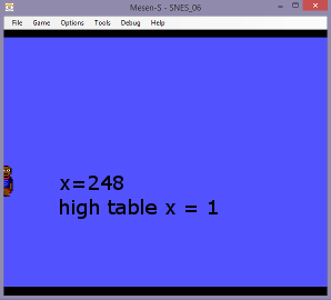
And this will automatically put all the data in the OAM_BUFFER at the correct x and y positions. It also adjusts the high table bit shifting and keeps track of exactly how many sprites have been added (sprid).

*spr_x is 9 bits (uses 2 bytes). If the sprite never leaves the screen, just leave the upper byte of spr_x as zero. If you pass it more than 9 bits, it will ignore the extra bits.

The ball uses another function, OAM_Spr. This is for putting 1 sprite in the OAM BUFFER. You have to provide all the details of the sprite. Pass the x position to spr_x, the y position to spr_y, the tile # to spr_c, the attributes to spr_a, and set the size with spr_sz. spr_sz needs to be either 0 (small) or 2 (large). Then jsr OAM_Spr.

lda ball_x
sta spr_x
lda ball_y
sta spr_y
lda #2
sta spr_c
lda #SPR_PAL_5|SPR_PRIOR_2
sta spr_a
stz spr_sz ;8×8
jsr OAM_Spr

If you are placing multiple balls on screen, all using the same palette, then you would only need to change the spr_x and spr_y before calling OAM_Spr again.

Writing to the background

The print_score function always runs during v-blank. It has to, because it is writing to the VRAM. That is why we do it as soon as possible after the jsr Wait_NMI.

I’m using this Map_Offset function (in library.asm) to get the VRAM address of the numbers in at the top of the screen. It wants you to load X with the tile’s x position 0-31 and load Y with the tile’s y position 0-31. If you only have pixel X and Y, just shift right (lsr a) 3 times to get the 0-255 value to 0-31 (tile) for 8×8 tiles.

Map_Offset does some bit shifting to convert that to a VRAM address. It returns A16 = the offset. You add that to the base address (our BG3 map is at $7000).

ldx #12
ldy #1
jsr Map_Offset ; returns a16 = vram address offset
clc
adc #$7000 ;layer 3 map
sta VMADDL ;$2116

and then copying 2 values per number on screen (by writing to $2118-$2119). We are writing with the VRAM increment set to +32. That means that the second write will go below the first one.

lda #V_INC_32
sta VMAIN ;$2115

Some of these values might be hard to understand, like, why are we adding $10 to the points_L? Our tiles for numbers begins at $10.

Try the demo. Press START to get it going.

Example7

.
Try to make this into a game by having controller 2 to move the right paddle.

The ball is a bit slow, though. Moving 2 pixels per frame might be too fast. It would be best to use “fixed point” math, that’s a 16-bit variable for ball speed and position, where the upper byte refers to a pixel position, and the lower byte is a sub-pixel position (and speed). Then we could have 1 1/2 pixel per frame movement.

I wish we had some sound effects too. Maybe a little later for that.
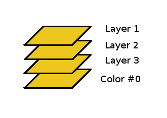
SNES main page

Controllers and NMI

SNES programming tutorial. Example 6.

https://github.com/nesdoug/SNES_06

.

Warning – this was made with SPEZ, version 2. Version 3’s default metasprite data breaks the code used in the example because it has 2 extra bytes for flipping the metasprite horizontally and/or vertically. If you use version 3 with the code below, you need to uncheck ‘flip data’. Or, you could use the metasprite code provided with SPEZ v3 in the ‘example’ folder. Or, a third option, you can still download version 2 of SPEZ.

https://github.com/nesdoug/SPEZ

.

Controller reads

There is a set of registers that can be read like NES registers. Originally, they wanted to make it easy to transition from programming NES games to programming SNES games. They even used the same number $4016 and $4017 (ports 1 and 2). However, you shouldn’t read these. Instead you should turn on the auto-read feature (and also the NMI enable) from register $4200.

With auto-controller reads set, the CPU be interrupted (soon after the end of each frame) and automatically read all the buttons from both controllers and then store the values at $4218-$421b.

$4218-19 port 1
$421a-1b port 2
(if a multitap for 4 player games installed, 421c-d and 421e-f for controllers 3+4)

The button order is…
KEY_B = $8000
KEY_Y = $4000
KEY_SELECT = $2000
KEY_START = $1000
KEY_UP = $0800
KEY_DOWN = $0400
KEY_LEFT = $0200
KEY_RIGHT = $0100
KEY_A = $0080
KEY_X = $0040
KEY_L = $0020
KEY_R = $0010

And I use these constants as a bit mask (bitwise AND operation) to isolate the buttons.

The pad_poll function also does some bit twiddling to figure out which buttons have just been pressed this frame.

pad1 and pad2 variables tell you which buttons are being pressed.
pad1_new and pad2_new tell you which buttons have just been newly pressed this frame.
We need call pad_poll each frame. How do we know that a new frame has started? That’s where the NMI comes in.

NMI

When the screen is on, the PPU spends most of its time drawing pixels to the screen, one horizontal line at a time, one pixel at a time. Starting at the top, it goes left to right and draw a line. Then it jumps down and draws the next line. Etc, etc, until the frame is completed.

While it is drawing pixels to the screen, the PPU is busy, you can’t send new data to the VRAM. You can’t send new data to the  OAM or the CGRAM (palette) either. After the screen is done drawing, the PPU rests in a vertical blank period for a little bit. During this v-blank period, you CAN access the PPU registers.

If you turn on NMI interrupts, when the PPU is done drawing to the screen… nearly at the very beginning of v-blank, the PPU sends an NMI signal to the CPU. This happens every frame, which is 60 times a second (50 in Europe). That signal causes the CPU to pause and jump to the NMI vector (an address it finds at $00ffea in the ROM). We have it set to jump to the label called NMI: which is located in the init.asm file. (note, the NMI code needs to be in the 00 bank).

The NMI code is just this.

bit $4210 *
inc in_nmi
rti

* ; it is required to read this register during NMI

(many game have much more elaborate NMI code than this)

Our main code is waiting for the in_nmi variable to change. When it changes we know that we are in the v-blank period. Now is a good time to write to PPU registers or send data to the VRAM. But, also, we are using this to time our game loop.

wait_nmi: waits until we are in v-blank. We call this at the top of the game loop. Notice that I put a WAI (wait for interrupt) instruction here. If you neglected to turn NMI interrupts on, this would crash the game, as it waits forever for a signal that never comes. IRQ interrupts could also trip the WAI instruction, which is why I also wait for the in_nmi variable to change to be sure. You could delete the WAI instruction, if you would like*. Some games use this waiting loop to spin a random number generator. You could do that as well…. like adding a large prime number over and over, or just ticking a variable +1 over and over.

* someone told me that WAI could make an emulator run less laggy, as it would have less to do each frame. It also saves electricity, because the CPU uses less while it waits. You decide if you need it or not.

Soon after the wait_nmi function runs, we run our DMA to the OAM (copy our sprite buffer to the sprite RAM). This needs to be done during v-blank, which is why we do it first. Then, we run our pad_poll to read new button presses. Then we enter the game logic. Here’s an example of what we are doing to move the sprite.

Our sprite is composed of 3 sprites that move together (16×16 each). Each time we press the right button, we need to increase the X value of each sprite. Left, we decrease the X values. Each sprite uses 4 bytes, so each sprite X value is 4 bytes apart. So we do this…

  AXY16
  lda pad1
  and #KEY_LEFT
  beq @not_left
@left:
  A8
  dec OAM_BUFFER ;decrease the X values
  dec OAM_BUFFER+4
  dec OAM_BUFFER+8
  A16
@not_left:

LDA loads the A register with pad1, which has all the button presses for controller 1. We apply a bit mask (AND) to isolate the left button. If it is zero, the button isn’t being pressed, and it will branch (BEQ) over our code. Otherwise, it will then to the dec OAM_BUFFER lines. Dec can be 8 bit or 16 bit, depending on the size of the A register. We want 8 bit, so we A8 for that. We need the A16, to make sure we exit this bit of code with A always in 16 bit mode.

We repeat that process 3 more times for RIGHT, UP, and DOWN buttons. You see, our character moves around the screen. This code isn’t very good, though. We aren’t handling that 9th X bit.

With this code, you can move smoothly off the top and bottom of the screen, like this…

example6b

But if you try to move left off screen, it suddenly disappears. Like this below…

example6d

example6f

That’s why we need that 9th X bit in the high table. Here’s what it looks like at X=248, with the 9th bit = 0.

example6c

And below shows what the same X=248, with the high table (9th bit) = 1

example6e

We didn’t do that in this example, but I worked up some code that can manage this. If you look in the next example files, in the library.asm file, you will see the functions called OAM_Spr and OAM_Meta_Spr. The spr_x variable is 9 bit so that we can move a sprite object smoothly off the left side without suddenly disappearing.

https://github.com/nesdoug/SNES_07/blob/master/library.asm

To use OAM_Spr, first we set the variables spr_x, spr_y, spr_c (tile), spr_a (attributes), and spr_sz (size), then call this function, and it will load the OAM buffers with the appropriate values (and also handle that awkward high table).

To use OAM_Meta_Spr, we first set spr_x, and spr_y, and then load the A and X registers with the address of the metasprite data. (A16 with absolute address, and X with the bank #). The metasprite data is generated by SPEZ and it is a list of each sprite in the multi-sprite object (5 bytes per sprite). This function will automatically calculate the relative position of each sprite, and write them in the OAM buffers.

.

SNES main page

Sprites

SNES programming tutorial. Example 5.

https://github.com/nesdoug/SNES_05

Sprites are the graphic objects that can move around the screen. Nearly all characters are made of sprites… Mario, Link, Megaman, etc. The OAM RAM controls how each sprites appear.

Mario

You will notice that Mario is made of 2 16×16 sprites. It is common to use more than 1 sprite for a character. Rex is also made of 2 16×16 sprites, with the lower sprite several pixels to the right of the top one. You can also layer sprites on top of each other, but with 15 colors to choose from, you shouldn’t have to.

You could increase the large sprite size to 32×32, but that would end up wasting more VRAM space on blank spaces. 8×8 and 16×16 are more common. I call it a “metasprite” when it is a collection of multiple sprites to make up 1 character. The SPEZ sprite editor I wrote saves these as tables of numbers HOWEVER I didn’t do that this time. This time I manually typed the sprite values in main.asm at the Sprites: label. In SPEZ, I saved the tiles and palette, which we .incbin at the bottom of main.asm.

https://github.com/nesdoug/SPEZ

You may prefer to draw your sprites in another tool, and import those images into SPEZ.

spez

OAM

The official docs call sprites “objects”. You need to write data to the OAM RAM to get them to show up on screen.

There are 2 tables in the OAM, and you need to write both of them, usually a DMA during v-blank or forced blank.

Low Table

The low table (512 bytes) is divided into 4 bytes per Sprite, with sprite #0 using bytes 0,1,2,3 and sprite , #1 using bytes 4,5,6,7, etc… up to sprite #127. 4 x 128 = 512 bytes.
Those bytes are, in this order…

byte 1 = X position

byte 2 = Y position

byte 3 = Tile #

byte 4 = attributes
.
X and Y are screen relative, in pixels (for the top left of the sprite).

Attributes

vhoopppN
v vertical flip
h horizontal flip
oo priority
ppp palette
N 1st or 2nd set of tiles (you can have up to 512 tiles for sprites).

The High Table

There are 32 bytes in the high table for 128 sprites. That’s 2 bits per sprite, and it can be very tedious to manage. Lots of bit shifting. The bits are

sx (s upper bit, x lower bit)
s= size (small or large)
x = 9th bit for x

The extra X bit is so you can smoothly move a sprite off the left side of the screen. With that bit set and the regular X set to $ff, that would be like -1. Whereas, without the extra X bit, $ff would be the far right of the screen, with only 1 pixel wide showing.

How are the 2 bits put together?
Let’s say,
Sprite 0 = aa
Sprite 1 = bb
Sprite 2 = cc
Sprite 3 = dd
The the first byte of the high table is
ddccbbaa
or (dd << 6) + (cc << 4) + (bb << 2) + aa

Palettes

Sprites use the second half of the CGRAM (palette). It is 15 colors + transparency for each palette. Sprite palette #0 uses indexes 128-143. Sprite palette #1 uses indexes 144-159. And so forth.

Priorities

I like to set sprite priority to 2. That would be in front of bg layers (but behind layer 3 if it’s set as super-priority in front of everything). Higher sprite priority would be in front of sprites with lower priority.

Besides priorities…Low index sprites will go in front of higher index ones. Sprite #0 would be in front of Sprite #1. Sprite #1 would be in front of Sprite #2. Sprite #2 would be in front of Sprite #3. Etc.

There is a limit to how many sprites can fit on a horizontal line. And using larger sprites doesn’t improve that, internally it splits sprites up into 8×1 slivers, and only 32 slivers can fit on a line. The 33rd one disappears. Because of this, you could shuffle the sprites every frame. That’s a lot of sprites, so I see most games just ignore this problem, and try not to put too many sprites on each line. Space shooter games (lots of sprites on screen at once) re-order the sprites in the OAM manually every frame. Some kind of shuffling algorithm, to make sure no bullets hit you that you couldn’t see.

Caution. Don’t put sprites at X position 0x100. (with the 9th bit 1 and the regular X at 00) They will be off screen, but will somehow count towards the 32 sprites per line limit.

Clearing Sprites

If you leave the OAM zeroed, it will display sprites at X=0, Y=0, Tile=0, palette=0… and the top left of the screen would have 128 sprites on top of each other. If you just want ALL sprites off screen, you could just turn them off from the main screen ($212c). But to put an individual sprite off screen, you should put its Y value at 224 (assuming screens are left to the default 224 pixel height). This would put 8×8,16×16, and 32×32 sprites off screen, but 64×64 sprites would wrap around to the top of the screen… so maybe don’t use 64×64 sprites (or make sure to set its size to small before pushing it off screen).
.

Let’s go over the code.

Code

We need to change a few settings, first.
$2101 sets the sprite size and the location of the sprite tiles.
sssnnbbb
sss = size mode*
nn = offset for 2nd set of sprite tiles. leave it at zero, standard.
bbb = base address for the sprite tiles.
Again, the upper bit is useless. So, each b is a step of $2000.

* size modes are

000 = 8×8 and 16×16 sprites
001 = 8×8 and 32×32 sprites
010 = 8×8 and 64×64 sprites
011 = 16×16 and 32×32 sprites
100 = 16×16 and 64×64 sprites
101 = 32×32 and 64×64 sprites

.

lda #2
sta OBSEL ; $2101 sprite tiles at VRAM $4000, sizes are 8×8 and 16×16

And we need to make sure sprites show up on the main screen.

lda #$10 ; sprites active
sta TM ; $212c main screen

https://wiki.superfamicom.org/sprites

https://wiki.superfamicom.org/registers

From here on out, I am going to use BUFFERS. Buffers are temporary locations in local RAM that will be copied (DMA) each frame to the actual memory (the OAM RAM)… during the v-blank period. Well, next time we will do that. In this example, we are doing it once during forced blank (2100 bit 7 set), which is also fine.

We are using a block move macro to copy from the ROM to the BUFFER.

BLOCK_MOVE 12, Sprites, OAM_BUFFER

to set up a MVN operation (to copy a block of data from the ROM to the RAM). See macros.asm for details.

And I’m writing just one byte to the high table. We only need 3 sprites in this example, so we will only need 2×3=6 bits, setting the size of each to large (16×16).

lda #$6A ;= 01 101010
sta OAM_BUFFER2

Now I will DMA both tables at once. A DMA to the OAM looks like this… [sorry, I changed the code a bit, but this is essentially the same thing.] jsr DMA_OAM will do this…

; DMA from OAM_BUFFER to the OAM RAM
ldx #$0000
stx $2102 ;OAM address

stz $4300 ; transfer mode 0 = 1 register write once
lda #4 ;$2104 oam data
sta $4301 ; destination, oam data
ldx #.loword(OAM_BUFFER)
stx $4302 ; source
lda #^OAM_BUFFER
sta $4304 ; bank
ldx #544
stx $4305 ; length
lda #1
sta $420b ; start dma, channel 0

That’s 544 bytes being copied to the $2104 (OAM DATA register) after we zeroed the OAM address registers ($2102-3). I recommend always writing to the OAM with a 544 byte DMA, once per frame (during v-blank).

The data we are transferring looks like this…

Sprites:
;4 bytes per sprite = x, y, tile #, attribute
.byte $80, $80, $00, SPR_PRIOR_2
.byte $80, $90, $20, SPR_PRIOR_2
.byte $7c, $90, $22, SPR_PRIOR_2

With the top left sprite at x = $80 and y = $80. We are using tiles 00,20,22, and all of the sprites use palette #0 and priority #2 (above BG layers).

And this is what it looks like.

example5

Try drawing your own sprite, and getting it to show up on screen.

SNES main page

Layers / Priority

SNES programming tutorial. Example 4.

https://github.com/nesdoug/SNES_04

Last time we created a background (tiles and map) and got it to show up on screen. This time we are going to add more layers.

In Mode 1, we get 3 background layers. Layer 1 and 2 are 4bpp (16 color) and Layer 3 is 2bpp (4 color). I made the graphics in GIMP and resized to 256×256 or less (the moon was 112×128, the text was 256×32).

Now I imported these into M1TE. The moon was imported while Layer 1 (4bpp) was active. The text was imported while Layer 3 (2bpp) was active. I just drew some moon tiles in blue on Layer 2 (also 4bpp).

bg1 layer 1

bg2 layer 2

bg3 layer 3

Now let’s talk about how the layers work. Normally, layer 1 is on top, then layer 2 is next, and layer 3 on the bottom. Like this.

Example4

But each tile on the map has a PRIORITY setting. Normally, this is to determine if the BG tile will go behind a sprite on the same layer, or in front of it. In mode 1, the layers go like this…

(top)
Sprites with priority 3
BG1 tiles with priority 1
BG2 tiles with priority 1
Sprites with priority 2
BG1 tiles with priority 0
BG2 tiles with priority 0
Sprites with priority 1
BG3 tiles with priority 1
Sprites with priority 0
BG3 tiles with priority 0
(bottom)

Anywhere there is color #0 on a tile, it will be transparent on that layer. Behind all the layers (if there isn’t a solid pixel on any layer) it will be filled with color #0.

Layers

However, if bit 3 of $2105 is set, BG3 will be in FRONT of everything (if the priority bit is set on the map). In M1TE, you can set all the priority bits for the whole map by checking a box.

Priority

I did that for BG3. The only difference between the picture above and below is the bit 3 of $2105 is set. (see these links for reference)

https://wiki.superfamicom.org/registers

https://wiki.superfamicom.org/backgrounds

Example4b

With $2105 d3 set and priority bits in BG3 map set, they appear on top. This can be very useful for text boxes that appear in front of everything, or a HUD / Scoreboard that you can always see. Because BG3 is only 2bpp, it won’t be very colorful, so it will be ideal for text messages.

The code for putting all this together is very similar to the previous page. The 2bpp tiles were loaded to $3000 in the VRAM with a DMA.

ldx #$3000
stx VMADDL ; set an address in the vram of $3000

lda #1
sta $4300 ; transfer mode, 2 registers 1 write
lda #$18 ; $2118
sta $4301 ; destination, vram data
ldx #.loword(Tiles2)
stx $4302 ; source
lda #^Tiles2
sta $4304 ; bank
ldx #(End_Tiles2-Tiles2)
stx $4305 ; length
lda #1
sta $420b ; start dma, channel 0

and the maps were loaded similarly with DMAs. BG2 map to $6800 and BG3 map to $7000. The maps for those layers will then be loaded to those VRAM addresses. We need to tell the PPU where our tiles and maps are.

stz BG12NBA ; $210b BG 1 and 2 TILES at $0000

lda #$03
sta BG34NBA ; $210c put BG3 TILES at VRAM address $3000

lda #$60 ; bg1 map at VRAM address $6000
sta BG1SC ; $2107

lda #$68 ; bg2 map at VRAM address $6800
sta BG2SC ; $2108

lda #$70 ; bg3 map at VRAM address $7000
sta BG3SC ; $2109

We need to make sure that all 3 layers are active on the main screen.

lda #BG_ALL_ON ;$0f
sta TM ; $212c

and that will give us this picture (same as above)

Example4

with BG3 behind everything.

When we flip bit 3… 00001000 at $2105, BG3 will show up on top (if their priority bits are set on the map). Note BG3_TOP is defined as 8.

lda #1|BG3_TOP ; mode 1, tilesize 8×8 all, layer 3 on top
sta BGMODE ; $2105

Like this.

Example4b

Each of these layers scroll independently of each other. You would adjust them with these registers. They are write twice (low then high).

$210d – BG1 Horizontal

$210e – BG1 Vertical

$210f – BG2 Horizontal

$2110 – BG2 Vertical

$2111 – BG3 Horizontal

$2112 – BG3 Vertical

(Note: not used in this example)

Maps, In Depth

All of our examples are with maps set to 32×32 tiles. (the screen is set to 224 pixels high, so you can’t see all the tiles at once). Each address in the map uses 2 bytes, since the VRAM is set up for 16 bits per address. It can be very confusing to look at in a Hex Editor (VRAM memory viewer) that show bytes, you will have to multiply x2 the VRAM address to find it in the hex editor. VRAM address $6000 is going to be found at $C000 in the emulator’s memory viewer.

Each map uses $800 bytes, but only $400 addresses (32×32 = 1024 = $400). They would be arranged like…

0,1,2,3,4… 31 =  1st row / top of screen
32,33,34,35… 63 = 2nd row
64,65,66,67… 95 = 3rd row
etc. on down to 32nd row, below the bottom of the screen

So, if you go down 1 on the map, you add 32 to the address.

Larger Maps

Maps

We could have made the map 64 tiles wide (for BG1 $2107, bit 0 = 1). If the left screen is at $6000, the right screen would be at $6400. In M1TE, you could construct each 32×32 part as a separate map.

We could have made the map 64 tiles tall (for BG1 $2107, bit 1 = 1). The upper screen at $6000 and the lower screen at $6400.

Lastly, if we made the map 64×64 (for BG1, both bits 0 and 1 set). If the first screen is at $6000, the screens would be arranged like

$6000 – $6400

$6800 – $6c00

If tiles were set to 8×8 size ($2105, called “character size”), a 64×64 map would be 512×512 pixels in size.

If tiles were set to 16×16, the same map would be 1024×1024 pixels. This should explain why we need 16 bit scrolling registers.

Tiles in the Map

So, I said that each entry in the map is 16 bits. Those bits are arranged like this…

vhopppcc cccccccc
v/h = Vertical/Horizontal flip this tile.
o = Tile priority.
ppp = Tile palette.
cc cccccccc = Tile number.

Each tileset is theoretically as big as 1024 tiles (for BG).

And, one more thing about palettes.

Palettes in Mode 1

Palette2

4bpp tiles use an entire row (left to right). If you set its palette to 0, it uses the top row (indexes 0-15). Palette 1, the next row (indexes 15-31), and so forth down to the 8th row (palette 7). That’s indexes 0 – 127 for background. Sprites would use the indexes 128 – 255 similarly. Sprites also use 4bpp tiles and 16 colors per tile.

2bpp tiles (BG3) shares the top 2 rows. Each palette only uses 4 colors, so palette 0 uses indexes 0-3, palette 1 uses index 4-7, palette 2 uses index 8-11, and palette 3 uses index 12-15… all in the top row. Palettes 4-7 similarly would use the next row. Every 0th color in each palette would be transparent. I usually reserve the top row for BG3 and the other 7 rows for BG1 and BG2.

Behind all the layers, the universal background color shows (index 0 of the palette), wherever there are transparent pixels. This is true for every layer. The black that fills most of these pictures is the background color showing through.

SNES main page

Backgrounds

SNES programming tutorial. Example 3.

https://github.com/nesdoug/SNES_03

So, this is the big lesson. There are about a dozen things we need to do just to see a picture on the screen. We need to set a video mode. We need to enable a layer on the main screen. We need to set the address for tiles. We need to set the address for a tilemap. We need to make tiles and a tilemap (and a palette). We need to copy all the things to the VRAM. And we need to turn screen brightness on (and end forced blank).

I picked a random picture of a moon. Open in GIMP, resize to 128×128. (a little later, the image looked stretched out when I got it running on my actual SNES, due to the aspect ratio of SNES pixels being about 8/7)… resize to 112×128 to fix the sideways stretching. Save as PNG.

Now get my background tool for SNES (Mode 1). It can import images (up to 256×256). It can do all the steps we need.

https://github.com/nesdoug/M1TE2

Import Image / get palette will auto generate an ideal 16 color palette.

Import Image / get tiles/map will turn the image into SNES graphics, and fill the map. Make sure the map height is 28. I used the arrows above the map editor to shift the image to the center. Now save… Save palette 16 colors (.pal). Save tiles 4bpp x 1 (.chr). Save maps just to the map height (.map).

These were added to the project by adding .incbin lines at the bottom of main.asm.

Now the code, which I will go over, line by line… but first I want to figure out where we are putting things in the VRAM. This is what I have been using, and it seems to work for my current needs. This arrangement is optional. You can rearrange the VRAM any way you like.

VRAM MAP

$0000 4bpp BG tiles (768 of them)
$3000 2bpp BG tiles (512 of them)
$4000 4bpp sprite tiles (512 of them)
$6000 layer 1 map (up to 2 screens)
$6800 layer 2 map (up to 2 screens)
$7000 layer 3 map (up to 2 screens)
$7800 layer 4 map (up to 2 screens)

So we need to put the 4bpp tiles at $0000 and the layer 1 map at $6000.

; DMA from Palette_Copy to CGRAM
; see previous tutorial page for that code


; DMA from Tiles to VRAM 
lda #V_INC_1 ; the value $80
sta VMAIN ; $2115 register, set the increment mode +1
; each write will go +1 the previous write address
ldx #$0000
stx VMADDL ; $2116 set an address in the vram of $0000

; now we set up the DMA
lda #1
sta $4300 ; transfer mode, 2 registers 1 write
; $2118 and $2119 are a pair Low/High
lda #$18 ; $2118
sta $4301 ; destination, vram data
ldx #.loword(Tiles)
stx $4302 ; source
lda #^Tiles
sta $4304 ; bank
ldx #(End_Tiles-Tiles)
; let the assembler calculate the size of transfer
; using 2 labels before and after our tiles.
stx $4305 ; length
lda #1
sta $420b ; start dma, channel 0


; DMA from Tilemap to VRAM 
ldx #$6000
stx VMADDL ; set an address in the vram of $6000

lda #1
sta $4300 ; transfer mode, 2 registers 1 write
; $2118 and $2119 are a pair Low/High
lda #$18 ; $2118
sta $4301 ; destination, vram data
ldx #.loword(Tilemap)
stx $4302 ; source
lda #^Tilemap
sta $4304 ; bank
ldx #$700
stx $4305 ; length
lda #1
sta $420b ; start dma, channel 0 


; a is still 8 bit.
lda #1 ; mode 1, tilesize 8x8 all
sta BGMODE ; $2105

stz BG12NBA ; $210b tiles for BG 1+2 at VRAM address $0000

lda #$60 ; bg1 map at VRAM address $6000
sta BG1SC ; $2107

lda #BG1_ON ; $01 = only bg 1 is active
sta TM ; $212c

lda #FULL_BRIGHT ; $0f = turn the screen on (end forced blank)
sta INIDISP ; $2100


Let’s go over these last lines. $2105 is for video mode. We want mode 1, and 8×8 tiles. Our tiles will need to be 4bpp for layers 1 and 2. (we are only using layer 1). The bits of $2105 are 4321Emmm, with mmm for BG Mode. E will affect priority of BG3. 4321 are zero so all the layers have 8×8 tiles. If any of these are set, the corresponding layer will have 16×16 tiles.

$210b tells the PPU where our tiles are (for layer 1 and 2). Low nibble for layer 1 and high nibble for layer 2. Our tiles are at $0000 so we are just storing zero. But if we wanted to, we could put our tiles at $1000 for layer 1 by storing #1 to 210b. They are steps of $1000.

This is the perfect opportunity to point out that for all these “VRAM address X is for Y” registers the upper bit is always zero. There are only $8000 VRAM addresses, and the registers always look like they go up to $FFFF, but they don’t. My guess is that the original engineers were told that there would be 128 kB of VRAM, but some bean counter said “128 kB is too expensive, we only need 64 kB”.

So, bbbb aaaa is really -bbb -aaa (a = layer 1, b = layer2).

So, for 210b, only values 0-7 make sense for each nibble.

Maps have 6 bits for VRAM address. They are steps of $400, but the low 2 bits of the $2107 register are for map size… aaaaaayx where a is VRAM address and yx is map size (is really -aaaaayx with upper bit always 0 since VRAM addresses don’t go above $8000). It looks like you are just multiplying by $100. The value $60 is for VRAM address $6000, where our tile map for layer 1 will go.

You can reference this page for more information.

https://wiki.superfamicom.org/backgrounds

And we need to turn on layer 1 on the main screen $212c. (It would look really weird if we turned on ALL layers right now. All the other maps are still set to $0000 where our tiles are).

My main focus was setting up a tool chain for putting an image on screen. Here’s what it looks like. Try to repeat the process with a different picture. Maybe something more colorful?

Example3

.

What’s that RLE folder?

Another option for M1TE files (map and tiles) is to save as .rle (run length encoding). It’s slightly more advanced than a simple rle. It is designed for map compression. Decompression should be done during Forced blank. First set a VRAM address, then use this macro: UNPACK_TO_VRAM [rle address]. That will decompress it (to $7f0000) and then copy it to the VRAM.

See mainB.asm for an example.

You may choose to leave everything uncompressed and skip the RLE stuff, and only use it if you run out of ROM space. You decide.

SNES main page

DMA palette

SNES programming tutorial. Example 2.

https://github.com/nesdoug/SNES_02

https://github.com/nesdoug/M1TE2

What we want to do is fill the palette. We could set up a loop that writes to the CGDATA register 512 times (register $2122). But there is a much faster way to do this called DMA (direct memory access).

https://wiki.superfamicom.org/dma-and-hdma

https://wiki.superfamicom.org/grog’s-guide-to-dma-and-hdma-on-the-snes

Ignore the HDMA stuff for now (which use the same registers). The main use for DMA is to write to $2104, $2118, and $2122 (OAM data, VRAM data, and CG data). DMA is just a hardware copy loop for transferring data from the CPU bus (ROM and RAM) to the PPU bus (VRAM, palette, and OAM). You should use a DMA when you are transferring more than a dozen bytes to any of these RAMs.

Another use of DMA, you can copy from ROM to WRAM, or from cartridge SRAM to WRAM. You first set the WRAM address registers $2181, $2182, and $2183, then you DMA to the WRAM data write register $2180. What it can’t do… It can’t copy from WRAM to WRAM. Trying to do this will fail. You need to use a MVN or MVP block move operation to do that.

The example code is for DMA to palette RAM (CGRAM). DMA needs to happen during *forced blank or during **v-blank. First you set up the transfer. There are 8 channels, but let’s focus on channel 0. All of these are 8 bit values.

* forced blank is when the PPU is off, register $2100 upper bit set.

** v-blank or vertical blank, happens once per frame when the the PPU is on. First the PPU will draw the entire screen, line by line, then it will pause slightly before it jumps back to the top. This pause is the vertical blank period, and the PPU is idle, so you can send new data to the VRAM and OAM and CGRAM during this time.

DMA Registers

$4300 to set up the transfer mode.

$4301 is the destination register $21xx. So, $04 = $2104. $18 = $2118. Etc.

$4302 is the source address, low byte

$4303 is the source address, high byte

$4304 is the source address, bank byte

$4305 is the number of bytes, low byte

$4306 is the number of bytes, high byte

Then, for channel 0, you write #1 to $420b to start the transfer. This locks up the CPU until the transfer is complete.

$420b is a bitfield, with each bit representing a different channel. Channel/bits 76543210. Only one DMA is performed at a time, and if you activate multiple channels with the same 420b write, they are performed sequentially, one at a time. DMA locks up the CPU, which will only focus on the DMA transfer, and not go to the next line of code until the DMA is complete.

$43×0 where x is the channel.

If you were using channel 1, the registers would be 4310,4311,4312,etc and you would write #2 to 420b. If you were using channel 2, the registers would be 4320,4321,4322,etc and you would write #4 to 420b. And so forth.

We are writing to the palette, we need to first zero the palette address, then send to $2122, the CG data register.

; DMA from BG_Palette to CGRAM
A8
XY16
stz CGADD ; $2121 cgram address = zero

stz $4300 ; transfer mode 0 = 1 register write once
lda #$22 ; $2122
sta $4301 ; destination, cgram data
ldx #.loword(BG_Palette)
stx $4302 ; source
lda #^BG_Palette
sta $4304 ; bank
ldx #256 ; BG_Palette only has 128 colors
stx $4305 ; length
lda #1
sta $420b ; start dma, channel 0

Note, I only transferred 256 bytes (128 colors). Let’s look at why.

I just used the default palette from the M1TE editor. This was designed for editing BG tiles, so the palette only has 128 entries. I thought having a ROM that was just a black screen would be dull, so I changed color #0 (the top left = the background color) to blue. Palette / Save.

default2

You can include a binary file using the .incbin directive (see bottom of main.asm). There is a label here BG_Palette: which we can reference in our code. I put it in an entirely different bank (RODATA1 segment is bank $81), just to show that it can be done easily.

Then I ran the DMA code twice to copy the same 256 bytes to both the BG palette (first 128 colors) and the Sprite palette (last 128 colors). It would be nice if you could just write #1 to $420b again, but the transfer changes some of the DMA registers (transfer length counted down to zero and the source address will be adjusted upward). So I had to rewrite the those and THEN write #1 to $420b.

When I run the ROM in MESEN-S, I can open the Palette Viewer tool, and see that our palette has been copied twice, as expected.

Palette

Well… we haven’t copied any actual tiles yet, so we can’t show anything but a plain screen. Try changing the color in M1TE to some other color, and reassembling and see if you can get it to work. This is what it looked like for me.

Example2

For reference, I will post the example code for DMA to VRAM and DMA to OAM. See also…

https://github.com/nesdoug/SNES_02/blob/master/DMA_Examples.txt

;DMA to VRAM 
A8
XY16
lda #$80
sta $2115 ; set the increment mode +1
ldx #$0000
stx $2116 ; set an address in the vram of $0000
; (and $2117)
lda #1
sta $4300 ; transfer mode, 2 registers 1 write
; $2118 and $2119 are a pair Low/High
lda #$18 ; $2118 vram data
sta $4301 ; destination
ldx #.loword(Tiles)
stx $4302 ; source
lda #^Tiles
sta $4304 ; bank
ldx #$2000
stx $4305 ; length
lda #1
sta $420b ; start dma, channel 0

.

;DMA from OAM_BUFFER to OAM
A8
XY16
ldx #$0000
stx $2102 ; oam address (and $2103)

stz $4300 ; transfer mode 0 = 1 register write once
lda #4 ;$2104 oam data
sta $4301 ; destination, oam data
ldx #.loword(OAM_BUFFER)
stx $4302 ; source
lda #^OAM_BUFFER
sta $4304 ; bank
ldx #544
stx $4305 ; length
lda #1
sta $420b ; start dma, channel 0

I will be covering these a little later.

On a side note. HMDA is a different thing altogether (but uses the same registers). It is for changing register values midscreen and it can change lots of different registers, such as mode 7 parameters, scroll registers, colors, mosaic, windowing, etc. You should be aware that there is a bug which happens if HDMA and DMA happen at the same time. It can crash the game (on the early revision SNES model). If you are using both, you might want to write #0 to $420c (the HDMA enable register) before performing a DMA, to disable HDMA.

More notes:

If you set a DMA transfer size of 0000, it will transfer 65536 ($10000) bytes.

You can set $43×0 to “fixed transfer” it will copy the same byte over and over, which can be used to fill VRAM, WRAM, etc. with zeros. The init code uses this technique.

.

SNES main page

SNES Example 1

Finally, some real programming!

https://github.com/nesdoug/SNES_01

Let’s do the simplest possible thing, to make sure that ca65 is working and we can get something to assemble correctly. We are going to turn the screen red.

Main.asm

.p816
.smart

.include "regs.asm"
.include "variables.asm"
.include "macros.asm"
.include "init.asm"

.segment "CODE"

  ;enters here in forced blank
main:
.a16 ;just a reminder of the setting from init code
.i16
  phk
  plb

  A8
  stz CGADD ; set color address to 0
  lda #$1f     ;palette low byte gggrrrrr
  sta CGDATA; 1f = all the red bits
  lda #$00     ;palette high byte -bbbbbgg
  sta CGDATA; store zero for high byte

  ;turn the screen on (end forced blank)
  lda #$0f
  sta INIDISP ;$2100

InfiniteLoop:
  jmp InfiniteLoop

.include "header.asm"

Notice that every asm file is included into the main file. That is to keep our compile.bat as simple and error proof as possible. I have put the SNES_01 folder inside my cc65 folder, and so the path to the bin folder is ..\bin\

.

Let’s go over every line.

.p816 – puts the assembler in 65816 mode

.smart – tell the assembler to automatically adjust register size depending on REP / SEP changes (handled through macros like A8, AXY16, etc)

.include – all of our constants, macros, init code, and header file.

.segment “CODE” – where will our main code end up, in the CODE segment

main: – our label, where the init code jumps to at startup

.a16 / .i16 – this is what the register size was when it left init. These are assembler directives to set A and XY assembly to 16 bit size.

phk / plb – not that important here, but sets the Data Bank Register to the same as the Program Bank (which is currently $80, a mirror of $00, and necessary for fastROM).

A8 – a macro to put the A register in 8 bit mode, I know it’s confusing since I just told the assembler to do A16 a second ago. If you like, you can delete the .a16 line since we change it right away, but I like to leave directives just to remind myself what the settings were just before we got here.

stz CGADD ;$2121 – set the palette address register to zero

lda #$1f – load A register with the value $1f – the low byte of the color $001f = red.

sta CGDATA ;$2122 – send the low byte to the palette (CGRAM)

lda #$00 – load A register with the value $00 – the upper byte of the color.

sta CGDATA ;$2122 – send the high byte to the palette

lda #$0f – full brightness, no forced blank
sta INIDISP ;$2100 – effectively turns the screen ON

$2100 hardware register bits… x- – -bbbb
x = forced blank if set (turns off screen rendering)… $80
b = screen brightness, from 0 = black to $0f = full brightness

InfiniteLoop:
jmp InfiniteLoop – will jump repeatedly to this line

Now, we did NOT activate anything on the “main screen”, such as layers 1,2,3, or 4, or sprites (objects). With nothing on main, only the background color will show, which is the 0th palette entry.

Note:

Each color is 15 bits, BGR (the upper bit should be 0). Try changing the color and re-assembling. If you run it in MESEN-S, remember to reload from file/open and not click on the picture of the file (which only reloads the savestate, rather than reloading from file).

-bbbbbgg gggrrrrr
black = $0000
red = $001f
green = $03e0
blue = $7c00
white = $7fff

Here’s what it looks like. It’s not much, but we need to start somewhere.

SNES_01

And, if you look at the palette viewer, you can see our color at index 0.

PaletteView

.

Before we go, I just want to briefly mention the other files here.

Init.asm is the RESET code (and a few other bits). It zeroes all the registers and RAM and gets us to square one, before jumping long to main. Don’t feel like you need to understand every line in this file. Focus on the main code for now.

macros.asm is a few assembler macro definitions, like A8, AXY16, etc.

regs.asm is a list of constants, the SNES hardware registers. Also there are some constants that I wrote that will help.

If you want to  read about the hardware registers, go here…

https://wiki.superfamicom.org/registers

variables.asm is a list of variables, which are in the “zeropage” or “BSS” (LoRAM) segments. There is just a little bit here used by the init code. We will add to this later.

And, lastly, the compiled ROM is the SNES_01.sfc file. This is what you should open in an emulator. I recommend the MESEN-S emulator. The usual file extension for SNES files are .sfc or .smc. SFC for Super Famicom and SMC for Super Magicom (a cartridge dumper / copier from the old days).

https://github.com/SourMesen/Mesen-S/releases

.

By the way, I had written a library of code (EasySNES), but I did not use most of it here. I was discussing the matter with some friends, and I feel that SNESdev could be taught better with simpler examples, and the library will just obfuscate what is really going on.

(SNESdev SNES SFC Super Nintendo Super Famicom programming tutorial)

.

My apologies, since this first tutorial is essentially the same as this one…

https://wiki.superfamicom.org/writing-your-first-snes-program

I didn’t copy it. We just both coincidentally arrived at the same first step. Oh well. The next steps will be different.

SNES main page

How ca65 works

SNES game development, continued…

.

Just one more subject before we can actually get to write our SNES program. Using the assembler. You should have read some of the 6502 tutorials and read up on 65816 assembly basics… before heading any further.

First, we need to write our program in a text editor. I use Notepad++. You can use any similar app that can save a plain text file. We will save our files as .s or .asm. It might help if you include a path to the ca65 “bin” folder in environmental variables, so windows can find it. You can also just type a path in the command prompt, which will tell the system to look for ca65 and ld65 in the bin folder, which is one level up from the current directory.

set path=%path%;..\bin\

ca65 is a command line tool. If you just double click ca65, a box will open and then close. To run it, you need to first open a command prompt (terminal). To open a command prompt in Windows 10, you click on the address bar and type CMD. A black box should appear. You would type something like…

ca65 main.asm -g

for each assembly file. The -g means include the debugging symbols. If it assembles correctly, you should have .o (object files) of the same name. Then you use another program ld65 (the linker) to put them all together using a .cfg file as a map of how all the peices go together.

ld65 -C lorom256k.cfg -o program1.sfc main.o -Ln labels.txt

The -C is to indicate the .cfg filename (lorom256k.cfg). The -o indicates the output filename (program1.sfc). Then it lists all the object files (there is only 1, main.o). Finally, the -Ln labels.txt outputs the addresses of all the labels (for debugging purposes).

I use a batch file to automate the writes to the command line. Instead of opening a command prompt box, I just double click on the compile.bat file. I don’t want to go into detail about writing batch files, but mostly you will just need to add a ca65 line for each assembly file (unless they are “included” in the main assembly file, in which case they become part of that asm file). Then edit the ld65 line to include all object files.

Here’s some links to the ca65 and ld65 documents.

https://cc65.github.io/doc/ca65.html

https://cc65.github.io/doc/ld65.html

.

Take a look at some of my example code, such as this one.

https://github.com/nesdoug/SNES_01

It has a .cfg file and some basic assembly files just to get to square one. There is some initial code (init.asm), which zeroes the RAM and the hardware registers back to a standard state. We don’t want to touch that code. It works. Then there is a header section of the ROM so that emulators will know what kind of SNES file we have (see header.asm).

.segment “SNESHEADER”
;$00FFC0-$00FFFF

.byte “ABCDEFGHIJKLMNOPQRSTU” ;rom name 21 chars
.byte $30 ;LoROM FastROM
.byte $00 ; extra chips in cartridge, 00: no extra RAM; 02: RAM with battery
.byte $08 ; ROM size (2^# kByte, 8 = 256kB)
.byte $00 ; backup RAM size
.byte $01 ;US
.byte $33 ; publisher id
.byte $00 ; ROM revision number
.word $0000 ; checksum of all bytes
.word $0000 ; $FFFF minus checksum

The checksum isn’t actually important. If it’s wrong, nothing bad will happen. The important line is the one that says “LoROM FastROM” after it.

And there are VECTORS here. The vectors are part of how the 65816 chip works. It is a table of addresses of important program areas. The reset vector is where the CPU jumps when the SNES is first turned on, or if the user presses RESET. There are some interrupt vectors like NMI and IRQ which we can discuss later. The important thing is that our reset vector points to the start of our init code, and that the end of the init code jumps to our main code. Also, our reset code MUST be in bank 00.

;ffe4 – native mode vectors
COP
BRK
ABORT (not used)
NMI
RESET (not used in native mode)
IRQ

;fff4 – emulation mode vectors
COP (not used)
(not used)
ABORT (not used)
NMI
RESET (yes!)
IRQ/BRK

.

Let’s talk about the basic terminology of assembly files.

Constants

Foo = 62

They look like this. Foo is just a symbol that the assembler will convert to a number at compile time. It should go above the code that uses it.

LDA #Foo …becomes… LDA #62

.

Variables

There are 2 types of variables. BSS (standard) and Zero Page. On the SNES we call it Direct Page, but the assembler still calls it Zero Page. You have to put their definitions in a zeropage segment, which our linker file will specifically define as zeropage type (it will recognize this as a special type of RAM).

.segment “ZEROPAGE”

temp1: .res 2

This reserves 2 bytes for the variable “temp1”.

.segment “BSS”

pal_buffer: .res 512

This reserves 512 bytes for a palette buffer. Our linker .cfg file will probably define the BSS segment to be in the $100-$1fff range.

Our code will go in a ROM / read-only type segment.

.segment “CODE”

LDA temp1

STA pal_buffer

.

Labels

Main:
  LDA #1
  STA $100

Main: is a label. It should be flush left in the line. To the assembler, Main is a number, an address in the ROM file. We could then jump to Main…
jmp Main
or branch to Main…
bra Main

One assembly file may not know the value of a label in another file. So we might need a .export Main in the file where Main lives, and a .import Main in the other file.

.

Instructions

Also called opcodes. These are 3 letter mnemonics that the assembler converts to machine code. Some assemblers require whitespace to be on the left of the instructions (such as a tab or 2-3 spaces). I don’t believe ca65 requires this, but you might as well follow that standard practice.

Code:
  LDA cats
  AND #1
  CLC
  ADC #$23
  STA cats
  JSR sleep

.

Comments

Use a semicolon ; to start a comment. The assembler will ignore anything after the semicolon. In the linker .cfg file, use # to start a comment.

.

Directives

These are commands that the assembler will understand.

.segment “blah”
.816
.smart
.a16
.a8
.i16
.i8
.byte $12
.word $1234

segment tells the assembler that everything below this should go in the “blah” segment. 816 tell it that we are using a 65816 cpu. smart means automatically set the assembler to 8-bit or 16-bit depending on SEP and REP instructions. a16 sets the assembler to generate 16-bit assembler instructions for the A register. a8 for 8-bit. i16 sets the assembler to have 16-bit index instructions. i8 for 8 bit index registers. “byte” is to insert an 8-bit value into the ROM ($12 in this example). “word” is to insert a 16-bit value into the ROM ($34 then $12 in this example).

There are many other directives. Here are some important ones…

.include “filename.asm”

to include an assembly language file in another file.

.incbin “filename.chr”

to include a binary (ie. data) file in an assembly file. This example, CHR, is a graphics file.

.

65816 specific precautions

The most important thing to be careful with is register size. Your code needs REP and SEP commands to change the register size ( I use macros called A8, A16, XY8, XY16, AXY8, and AXY16). If you have .smart at the top of the code, the assembler will automatically adjust the assembly to the correct register size when it sees a REP or SEP that affect the register size flags… but, it is a good idea to put the explicit directives in at the top of each function. We need to make sure that the function above it doesn’t set the wrong register sizes. Those directives are .a8 .i8 .a16 and .i16.

Just to clarify– .a8 is an assembler directive to change the assembly output. A8 is a macro that will output a SEP #$20, which (when executed) will set the CPU into 8-bit Accumulator mode. .smart will see the SEP #$20 and automatically set the assembly output to 8-bit. But there are still possible errors, for example, something like this…

Something_stupid:  
  A16 ;set A to 16 bit mode
  lda controller1
  and #KEY_B
  beq Next_Bit
  A8 ;set A to 8 bit mode
  lda #2
  sta some_variable
Next_Bit:

What do you think would happen? The assembler will think everything below A8 has the A register in 8 bit mode, including everything below Next_Bit, even though the beq could branch there with the processor still in 16 bit mode. This could crash or create unusual bugs. So, you should put an A16 directly after the Next_Bit label, to ensure registers are in a consistent size.

Also, you might want to bookend many of your subroutines with php (at the start) and plp (at the end) if the subroutine changes the processor size in any way. This will ensure that it returns safely from the subroutine with the exact processor size that it arrived with.

Alternatively, you could try to do have a consistent register size for most of your code. For example, keep the A register 8 bit and the XY registers 16 bit… or perhaps keep all registers 16 bit for 90% of the code. An approach like that would reduce REP SEP changes and have fewer potential register size bugs.

If the subroutine changes any other registers (such as the data bank register B) you should also push that to the stack at the beginning of the subroutine and restore it at the end.

It is common to have data, and the code that manages that data, in the same bank. An easy way to set the data bank register to the same bank that the code is executing in is PHK (push program bank) then PLB (pull data bank). I have seen code that jumps to another bank do this, to save/restore the original data bank settings…

PHB
PHK
PLB
JSR code
PLB
RTL

But, maybe we don’t need to do that at EVERY subroutine. The overhead would be quite tedious and slow.

.

Another precaution, if a subroutine ends in RTL, you must JSL to it. And if a subroutine ends in RTS, you must JSR to it. You will probably find these errors quickly, though, because your program will crash.

Finally

Let’s review the linker file. lorom256k.cfg.

# Physical areas of memory
MEMORY {
ZEROPAGE: start = $000000, size = $0100;
BSS: start = $000100, size = $1E00;
BSS7E: start = $7E2000, size = $E000;
BSS7F: start = $7F0000, size =$10000;
ROM0: start = $808000, size = $8000, fill = yes;
ROM1: start = $818000, size = $8000, fill = yes;
ROM2: start = $828000, size = $8000, fill = yes;
ROM3: start = $838000, size = $8000, fill = yes;
ROM4: start = $848000, size = $8000, fill = yes;
ROM5: start = $858000, size = $8000, fill = yes;
ROM6: start = $868000, size = $8000, fill = yes;
ROM7: start = $878000, size = $8000, fill = yes;

}

# Logical areas code/data can be put into.
SEGMENTS {
# Read-only areas for main CPU
CODE: load = ROM0, align = $100;
RODATA: load = ROM0, align = $100;
SNESHEADER: load = ROM0, start = $80FFC0;
CODE1: load = ROM1, align = $100, optional=yes;
RODATA1: load = ROM1, align = $100, optional=yes;
CODE2: load = ROM2, align = $100, optional=yes;
RODATA2: load = ROM2, align = $100, optional=yes;
CODE3: load = ROM3, align = $100, optional=yes;
RODATA3: load = ROM3, align = $100, optional=yes;
CODE4: load = ROM4, align = $100, optional=yes;
RODATA4: load = ROM4, align = $100, optional=yes;
CODE5: load = ROM5, align = $100, optional=yes;
RODATA5: load = ROM5, align = $100, optional=yes;
CODE6: load = ROM6, align = $100, optional=yes;
RODATA6: load = ROM6, align = $100, optional=yes;
CODE7: load = ROM7, align = $100, optional=yes;
RODATA7: load = ROM7, align = $100, optional=yes;

# Areas for variables for main CPU
ZEROPAGE: load = ZEROPAGE, type = zp, define=yes;
BSS: load = BSS, type = bss, align = $100, optional=yes;
BSS7E: load = BSS7E, type = bss, align = $100, optional=yes;
BSS7F: load = BSS7F, type = bss, align = $100, optional=yes;

}

The memory area defines several RAM areas. Then it defines 8 ROM areas ROM0, ROM1, etc. Notice they all start at xx8000 and are all $8000 bytes (32kB). This is typical for LoROM mapping. In LoROM, the ROM is always mapped to the $8000-FFFF area. The 0-7FFF area is almost always a mirror of this…

$0-1FFF LoRAM (mirror of 7e0000-7e1fff)

$2000-$4FFF Hardware registers

In LoROM, we have access to these almost all the time with regular addressing modes.

The alternative is called HiROM, which can have ROM banks extend from $0000-FFFF. This doubles the maximum size of ROM, but makes access to LoRAM and Hardware Registers more awkward. This tutorial won’t be using HiROM.

You might notice that the bank is $80 instead of $00. $80 is a mirror of $00 (they access the same memory), but $80+ has faster ROM accesses, whereas $00 are slower. (you also need to change a hardware setting in the $420d register, and should indicate FastROM type in the SNES header). The game will reset into the $00 bank, and we need to jump long to the $80 bank to speed it up slightly.

On a side note, a 256kB ROM size is actually unusually small. 512 kB, 1 MB, 2 MB, and 4 MB are also possible. You should be able to double the size of the test ROMs with no trouble. Just double the number of ROM banks in the config file and in the header file. We won’t cover HiROM, but it also goes up to 4 MB (a few games managed up to 6 MB with a special board).

.

Ok. Some real code next time.


SNES main page


What you need, SNESdev

Before we start actually programming for the SNES, you will need a few things.

  1. An assembler
  2. A tile editor
  3. Photoshop or GIMP
  4. a text editor
  5. a good debugging emulator
  6. a tile arranging program
  7. a music tracker

65816 Assembler

I use ca65. It was designed for 6502, but it can assemble 65816 also. I am very familiar with it, and that is the main reason I use it. There is also WLA (which some other code examples and libraries use) and ASAR (which the people at SMWcentral use). For spc700 (which is another assembly language entirely) you could use the BASS assembler, by byuu/near.

http://cc65.github.io/cc65/

(Click on Windows snapshot)

Why not use cc65 c compiler? It doesn’t produce 65816 assembly, it produces 6502 (8 bit) assembly only. The code generated is totally inappropriate. There is the tcc816 c compiler, which works with the PVSnesLib. It compiles to the WLA assembler. Frankly, I just didn’t feel like learning these tools. But they are here, if you are interested.

https://github.com/alekmaul/pvsneslib

Link to the bass assembler, if you want to write your own SPC code. (This would be exceptionally difficult, and I won’t cover writing SPC programs).

https://github.com/ARM9/bass

These are command line tools. If you are not familiar with using command line tools, check out this link to catch up to speed. In windows 10, I have to click the address bar and type CMD (press enter) to open up a command line prompt. Watch a few of these tutorials to get the basics.

You might notice that I use batch files (compile.bat) to automate command line writes. You could use these or makefiles (which are a bit more complicated), to simplify the assembly process. I just double click the .bat file, and it executes all the assembling / linking commands.

Tile Editor

I prefer YY-CHR for most of my graphics editing. For 16 color SNES, change the graphic format to “4bpp SNES”. For 4 color SNES, change the graphic format to “2bpp GB”. The gameboy uses the same bitplane format as SNES.

The .NET version of YY-CHR has been improved, and can even do 8bpp SNES formats [EDIT – I can’t confirm that the 8bpp modes work right. They aren’t working for me. The 2bpp and 4bpp modes work.]. Here’s the current link for the better version.

https://w.atwiki.jp/yychr/sp/

Another very good app is called superfamiconv. It is a command line tool for converting indexed PNG (with no compression) to CHR files (snes graphic formats). It also makes palettes and map files. You could use it to convert your pictures to SNES format, and then later edit those files with YY-CHR.

The command line options are a bit complex, but it really does a fantastic job.

https://github.com/Optiroc/SuperFamiconv

Or you can use M1TE or SPEZ or M8TE (see below) for importing graphics and editing.

Photoshop or GIMP

GIMP is sort of a free image tool like Photoshop. You can use any similar tool to draw your art.

https://www.gimp.org/downloads/

You will have to resize the image to 256×256 or smaller and save as PNG before you can import it into M1TE. You might want to Image/Mode/Indexed and reduce to 16 color first before you save it. M1TE can reduce the color count, but I think GIMP is a bit better at it.

Text Editor

I use Notepad++. You could use any text editor, even plain old Notepad. You need to write your assembly source code with a text editor.

https://notepad-plus-plus.org/download/

Debugging Emulator

I have used several emulators in the past. This year (2020) the emulator to use is MESEN-S. It is brand new, but it blows the other emulators away in terms of useful tools.

https://www.mesen.ca/

It has a Debugger with disassembly and breakpoints. Event viewer. Hex editor / memory viewer. Register viewer. Trace logger. Assembler. Performance Profiler. Script Window. Tilemap Viewer. Tile Viewer. Sprite Viewer. Palette Viewer. SPC debugger. I might write an entire page just on this emulator. It’s cool.

One note, for a developer. Make sure when you rebuild a file, that you don’t select it from the picture that pops up when you open MESEN-S, but rather always select the file from File/Open. Otherwise, it will auto-load the savestate, which is the old file before it was reassembled.

I also like to change the keyboard input settings. For some reason he has mapped MULTIPLE settings at the same time, and none of them exactly what I would choose. So Option/Input/Setup, click on each Key Setup and clear them all (clear key bindings button) and then manually set a keyboard key for each button. I like the ASZX for YXBA buttons and arrow for direction pad.

Tile Arranger

I have been trying to make my own tools for SNES game development. M1TE (mode 1 tile editor) is for creating background maps (and palettes and tiles). SPEZ is for creating meta sprites that work with my own code system (Easy SNES). You may not need SPEZ, but definitely download M1TE.

One main benefit of M1TE is palette editing and conversions. It can load a YY-CHR style palette and output a SNES format palette. And the reverse. Remember not to name the SNES palette file as the same name as your CHR file and .pal extension, or YY-CHR will auto-load it as a RGB palette, and fail.

https://github.com/nesdoug/M1TE2

https://github.com/nesdoug/SPEZ

Go to the “Releases” page to download the exe file. They are .NET Windows app, and can also run on non-Windows computers with MONO.

M1TE

SPEZ

I recently made a new tool M8TE, which is the same as M1TE except it works for 8bpp tiles (Mode 3 or 7).

https://github.com/nesdoug/M8TE/

.

I also use Tiled Map Editor for creating data for games. You might find it useful.

https://www.mapeditor.org/

Music Tracker

I have been working with the SNES GSS tracker and system written by Shiru. I have been told there was a bug in the code that causes games to freeze. You might want to download the tracker from my repo, which has been patched to fix the bug. (it’s the snesgssQv2.exe file).

https://github.com/nesdoug/SNES_00/tree/master/MUSIC

and use the music.asm file here, since the original was written to work with tcc-816 and WLA. I rewrote it all in assembly for ca65.

.

You may want to use another music system. SNES MOD is a popular option (used with OpenMPT). Other systems are currently in development.

I think that’s enough for today. Next time, we can discuss using the ca65 assembler.

SNES main page