SNES programming tutorial. Example 4.
https://github.com/nesdoug/SNES_04
Last time we created a background (tiles and map) and got it to show up on screen. This time we are going to add more layers.
In Mode 1, we get 3 background layers. Layer 1 and 2 are 4bpp (16 color) and Layer 3 is 2bpp (4 color). I made the graphics in GIMP and resized to 256×256 or less (the moon was 112×128, the text was 256×32).
Now I imported these into M1TE. The moon was imported while Layer 1 (4bpp) was active. The text was imported while Layer 3 (2bpp) was active. I just drew some moon tiles in blue on Layer 2 (also 4bpp).
 layer 1
 layer 2
 layer 3
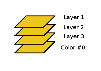
Now let’s talk about how the layers work. Normally, layer 1 is on top, then layer 2 is next, and layer 3 on the bottom. Like this.

But each tile on the map has a PRIORITY setting. Normally, this is to determine if the BG tile will go behind a sprite on the same layer, or in front of it. In mode 1, the layers go like this…
(top)
Sprites with priority 3
BG1 tiles with priority 1
BG2 tiles with priority 1
Sprites with priority 2
BG1 tiles with priority 0
BG2 tiles with priority 0
Sprites with priority 1
BG3 tiles with priority 1
Sprites with priority 0
BG3 tiles with priority 0
(bottom)
Anywhere there is color #0 on a tile, it will be transparent on that layer. Behind all the layers (if there isn’t a solid pixel on any layer) it will be filled with color #0.
However, if bit 3 of $2105 is set, BG3 will be in FRONT of everything (if the priority bit is set on the map). In M1TE, you can set all the priority bits for the whole map by checking a box.

I did that for BG3. The only difference between the picture above and below is the bit 3 of $2105 is set. (see these links for reference)
https://wiki.superfamicom.org/registers
https://wiki.superfamicom.org/backgrounds

With $2105 d3 set and priority bits in BG3 map set, they appear on top. This can be very useful for text boxes that appear in front of everything, or a HUD / Scoreboard that you can always see. Because BG3 is only 2bpp, it won’t be very colorful, so it will be ideal for text messages.
The code for putting all this together is very similar to the previous page. The 2bpp tiles were loaded to $3000 in the VRAM with a DMA.
ldx #$3000
stx VMADDL ; set an address in the vram of $3000

lda #1
sta $4300 ; transfer mode, 2 registers 1 write
lda #$18 ; $2118
sta $4301 ; destination, vram data
ldx #.loword(Tiles2)
stx $4302 ; source
lda #^Tiles2
sta $4304 ; bank
ldx #(End_Tiles2-Tiles2)
stx $4305 ; length
lda #1
sta $420b ; start dma, channel 0
and the maps were loaded similarly with DMAs. BG2 map to $6800 and BG3 map to $7000. The maps for those layers will then be loaded to those VRAM addresses. We need to tell the PPU where our tiles and maps are.
stz BG12NBA ; $210b BG 1 and 2 TILES at $0000
lda #$03
sta BG34NBA ; $210c put BG3 TILES at VRAM address $3000
lda #$60 ; bg1 map at VRAM address $6000
sta BG1SC ; $2107
lda #$68 ; bg2 map at VRAM address $6800
sta BG2SC ; $2108
lda #$70 ; bg3 map at VRAM address $7000
sta BG3SC ; $2109
We need to make sure that all 3 layers are active on the main screen.
lda #BG_ALL_ON ;$0f
sta TM ; $212c
and that will give us this picture (same as above)
with BG3 behind everything.
When we flip bit 3… 00001000 at $2105, BG3 will show up on top (if their priority bits are set on the map). Note BG3_TOP is defined as 8.
lda #1|BG3_TOP ; mode 1, tilesize 8×8 all, layer 3 on top
sta BGMODE ; $2105
Like this.
Each of these layers scroll independently of each other. You would adjust them with these registers. They are write twice (low then high).
$210d – BG1 Horizontal
$210e – BG1 Vertical
$210f – BG2 Horizontal
$2110 – BG2 Vertical
$2111 – BG3 Horizontal
$2112 – BG3 Vertical
(Note: not used in this example)
Maps, In Depth
All of our examples are with maps set to 32×32 tiles. (the screen is set to 224 pixels high, so you can’t see all the tiles at once). Each address in the map uses 2 bytes, since the VRAM is set up for 16 bits per address. It can be very confusing to look at in a Hex Editor (VRAM memory viewer) that show bytes, you will have to multiply x2 the VRAM address to find it in the hex editor. VRAM address $6000 is going to be found at $C000 in the emulator’s memory viewer.
Each map uses $800 bytes, but only $400 addresses (32×32 = 1024 = $400). They would be arranged like…
0,1,2,3,4… 31 = 1st row / top of screen
32,33,34,35… 63 = 2nd row
64,65,66,67… 95 = 3rd row
etc. on down to 32nd row, below the bottom of the screen
So, if you go down 1 on the map, you add 32 to the address.
Larger Maps
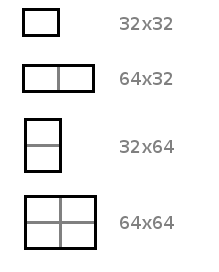
We could have made the map 64 tiles wide (for BG1 $2107, bit 0 = 1). If the left screen is at $6000, the right screen would be at $6400. In M1TE, you could construct each 32×32 part as a separate map.
We could have made the map 64 tiles tall (for BG1 $2107, bit 1 = 1). The upper screen at $6000 and the lower screen at $6400.
Lastly, if we made the map 64×64 (for BG1, both bits 0 and 1 set). If the first screen is at $6000, the screens would be arranged like
$6000 – $6400
$6800 – $6c00
If tiles were set to 8×8 size ($2105, called “character size”), a 64×64 map would be 512×512 pixels in size.
If tiles were set to 16×16, the same map would be 1024×1024 pixels. This should explain why we need 16 bit scrolling registers.
Tiles in the Map
So, I said that each entry in the map is 16 bits. Those bits are arranged like this…
vhopppcc cccccccc
v/h = Vertical/Horizontal flip this tile.
o = Tile priority.
ppp = Tile palette.
cc cccccccc = Tile number.
Each tileset is theoretically as big as 1024 tiles (for BG).
…
And, one more thing about palettes.
Palettes in Mode 1

4bpp tiles use an entire row (left to right). If you set its palette to 0, it uses the top row (indexes 0-15). Palette 1, the next row (indexes 15-31), and so forth down to the 8th row (palette 7). That’s indexes 0 – 127 for background. Sprites would use the indexes 128 – 255 similarly. Sprites also use 4bpp tiles and 16 colors per tile.
2bpp tiles (BG3) shares the top 2 rows. Each palette only uses 4 colors, so palette 0 uses indexes 0-3, palette 1 uses index 4-7, palette 2 uses index 8-11, and palette 3 uses index 12-15… all in the top row. Palettes 4-7 similarly would use the next row. Every 0th color in each palette would be transparent. I usually reserve the top row for BG3 and the other 7 rows for BG1 and BG2.
Behind all the layers, the universal background color shows (index 0 of the palette), wherever there are transparent pixels. This is true for every layer. The black that fills most of these pictures is the background color showing through.
