SNES programming tutorial. Example 11.
https://github.com/nesdoug/SNES_11
HDMA is a way to write to PPU registers while the screen is drawing. You can change values at specific scanlines, to create unique effects.
The H is for H-Blank. Remember before, when we talked about V-blank (vertical blank), where the PPU isn’t doing anything for a short while after drawing each screen? Well, it also pauses a VERY SHORT time after drawing each horizontal line. Just long enough for the 8 HDMA channels to quickly change a register or send data, before the screen goes to write the next line.
They work in order, 1,2,3,4,5,6,7,8. They can all write 1 thing (1,2 or 4 bytes) per line. Or you can set them to wait a specific number of lines before changing a value.
HDMA uses the same registers as the DMA registers, and you shouldn’t use both at the same time. You should write zero to HDMA enable ($420c) before performing a DMA. Because the oldest revision of the SNES has a bug where it can crash if they both happen at the same time. Or, just make sure they aren’t used at the same time.
Here’s an interesting video on DMA and HDMA.
Examples
Here’s some things you can do with HDMA.
Changing the BG color with HDMA, to create a color gradient.

Changing the Window (there are 2 windows) with HDMA, to block off portions of the screen. The windows have left and right registers, which need to be written every scanline to create these shapes.


Mode 7 parameters. (lots of registers to change hundreds of times a frame).
.
How HDMA works
https://wiki.superfamicom.org/registers
(for this link, scroll down to 43×0)
When you look at the HDMA registers, it looks like you need to put MORE values, but you don’t need to write to them all. Let’s go over each register.
For channel 0.
4300 – yes
4301 – yes
4302-4 – yes
4305-6 – no
4307 – yes, only if using Indirect Mode.
4308-a – no
4300 - Control Register. da---ttt
D=direction, probably want 0, from CPU to PPU.
A=HDMA mode. 0 for direct, 1 for indirect. More on this later.
TTT = transfer mode, which will vary by which register we use.
000 => 1 register write once (1 byte: p)
001 => 2 registers write once (2 bytes: p, p+1)
010 => 1 register write twice (2 bytes: p, p)
011 => 2 registers write twice each (4 bytes: p, p, p+1, p+1)
100 => 4 registers write once (4 bytes: p, p+1, p+2, p+3)
101 => 2 registers write twice alternate (4 bytes: p, p+1, p, p+1)
110 => 1 register write twice (2 bytes: p, p)
111 => 2 registers write twice each (4 bytes: p, p, p+1, p+1)
4301 – the PPU destination register. 21xx. So if you write $22 here, the HDMA will write to the $2122, the CGRAM Data Register.
4302-4 – the address of the HDMA table. 2=low, 3=middle, 4=upper/bank #.
4307 – if using Indirect HDMA, this is the bank # of the Indirect Addresses.
Anything marked “no”, don’t touch them. They are used by the HDMA hardware.
Then you write the channel (bitfield, each bit represents a channel, 1 for ch0, 2 for ch1, 4 for ch2, 8 for ch3, etc) to $420c, the HDMA enable register. Presumably, you would do this step during v-blank or during forced blank. I think it will misbehave for 1 frame if you turn HDMA on mid-frame.
.
OK, so we are pointing the HDMA registers to a table (byte array). For a direct mode, the table would be a scanline count, then (depending on the TTT mode) 1,2, or 4 bytes to be written. Then another scanline count, then more bytes. Scanline count, bytes. Scanline count, bytes. Etc, until it sees a zero in the scanline count slot. From my own examples…
H_TABLE6:
.byte 32, $0f
.byte 32, $1f
.byte 32, $2f
.byte 32, $4f
.byte 32, $6f
.byte 32, $9f
.byte 32, $ff
.byte 0 ;end
That reads 32 lines, value $0f. 32 lines, value $1f. 32 lines… etc down to the terminating 0. One interesting thing is that the $0f is written immediately at the very top of the screen. THEN it waits 32 lines.
Here’s another example, when the transfer mode is “1 register write twice”.
H_TABLE2:
.byte 10, 0, 0
.byte 10, 1, 0
.byte 10, 2, 0
.byte 10, 3, 0
.byte 10, 4, 0
.byte 10, 5, 0
.byte 10, 6, 0
.byte 10, 7, 0
.byte 10, 8, 0
.byte 10, 9, 0
...etc...
.byte 0 ;end
10 is the scanline count. Then 2 bytes to write. Then 10 scanline count. Then 2 bytes. Etc.
Indirect Mode
43×0 register, we can set it to Indirect. Only with indirect do you need to write to 43×7, the bank of the indirect address. The table will always be sets of 3s. First the scanline count, then an indirect address (ie. pointer) to where our data is. I wrote the HDMA table like this…
H_TABLE5:
.byte 8
.addr $1000
.byte 8
.addr $1002
.byte 8
.addr $1004
.byte 8
.addr $1006
.byte 8
.addr $1008
...etc...
.byte 0 ;end
The .addr directive outputs a 16 bit value, low byte then high byte. I think you could have also used the .word directive. So, 8 is the scanline count, then an indirect address. Our bank byte is $7e, so the first one points to WRAM $7e1000. The second one points to $7e1002. Etc.
One of the advantages of the indirect system is that you can have a repeated pattern that changes.
I had copied the Indirect Table to $7e1000. It looks like this.
IND_TABLE:
.byte 0, 0
.byte 3, 0
.byte 6, 0
.byte 7, 0
.byte 8, 0
.byte 7, 0
.byte 6, 0
.byte 3, 0
.byte 0, 0
.byte $fd, 0
.byte $fa, 0
.byte $f9, 0
.byte $f8, 0
.byte $f9, 0
.byte $fa, 0
.byte $fd, 0
.byte 0,0
All of these are values to be written with HDMA to a PPU register. In this case, a horizontal scroll register, which is write twice (low then high bytes).
This is example 3. I am also shuffling these values every 4 frames, which causes the movement of the the sine wave.
Example Code
No effect. HDMA is turned off by writing zero to $420c.

.
.
Example 1. Changing the BG color.
I’m actually setting up 2 separate HDMA transfers. First to set the CG address to zero. Second to write 2 bytes to change the #0 color. You have to rewrite the address each time, because it auto-increments when writing a color.
stz $4300 ;1 register, write once
lda #$21 ; CGRAM Address
sta $4301 ;destination
ldx #.loword(H_TABLE1)
stx $4302 ;address
lda #^H_TABLE1
sta $4304 ;address

lda #2
sta $4310 ;1 register, write twice
lda #$22 ; CGRAM DATA
sta $4311 ;destination
ldx #.loword(H_TABLE2)
stx $4312 ;address
lda #^H_TABLE2
sta $4314 ;address

lda #3 ;channels 1 and 2
sta HDMAEN ;$420c
And we have 2 HDMA tables (see the example code). Each time we are waiting 10 scanlines between changes. Each time, adding a little more red.

.
.
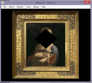
Example 2. Changing window 1 left and right positions.
A window punches a hole in one or more layer. There are 2 windows, but we only need 1 for this example. The only parameters you can set are left and right (and inverse, and combinations with the other window). But with HDMA, you can adjust the window parameters as the screen draws, and draw a shape. Circle shapes are very popular.
If the left position is > than the right position, the window will not appear. That is what we are doing for the top and the bottom of the screen. You also have to tell it which layers are affected with the $212e (window for main screen) and with the $2123-5 registers.
I’m using 2 HDMA channels, and writing 1 byte to 1 register. To 2126 and 2127.
lda #1 ;windows active on layer 1 on main screen
sta TMW ;$212e
lda #2 ;window 1 active on layer 1
sta W12SEL ;$2123

stz $4300 ;1 register, write once
lda #$26 ;2126 WH0
sta $4301 ;destination
ldx #.loword(H_TABLE3)
stx $4302 ;address
lda #^H_TABLE3
sta $4304 ;address


stz $4310 ;1 register, write once
lda #$27 ;2127 WH1
sta $4311 ;destination
ldx #.loword(H_TABLE4)
stx $4312 ;address
lda #^H_TABLE4
sta $4314 ;address

lda #3 ;channels 1 and 2
sta HDMAEN ;$420c
(This could have been done with 1 channel with a 2 register transfer mode).
Note… If the scanline count is >128 (not including 128), it signals a series of single scanline writes. You can omit the scanline count for a number of lines (ie. subtract 128 from the scanline count number).
.byte 60, $ff ;first we wait 60 scanlines
.byte $c0 ;192-128 = 64 lines of single entries
.byte $7f ;1st write value
.byte $7e ;2nd write value
.byte $7d ;3rd write value
.byte $7c ;4th write value
...etc...64 lines.
.byte 0 ;end
It waits 1 scanline between each write.
Each line, I am moving the left position and right position further apart, and then closer together, which forms a diamond shape.
.
.
Example 3. Changing BG1 horizontal scrolling position.
This was already discussed above, in the Indirect Mode section. We are using a sine wave pattern to create a wave in the picture, writing twice to 1 register, the horizontal scroll of BG1.
I wanted to include at least 1 example of indirect mode. I copied the value table to the RAM, so I was able to change the values to make the pattern move. See the Shuffle_f3 function in the HMDA3.asm file. The table of Indirect Addresses points to the RAM where our actual values are stored.
This example would have been even nicer if we wrote new values every scanline. Currently, we are only changing values every 8 scanlines (to make the table simpler / smaller). Maybe even every 2 scanlines would have been enough.
lda #$42 ;indirect mode = the 0100 0000 bit ($40)
sta $4300 ;1 register, write twice
lda #$0d ;BG1HOFS horizontal scroll bg1
sta $4301 ;destination
ldx #.loword(H_TABLE5)
stx $4302 ;address
lda #^H_TABLE5
sta $4304 ;address
lda #$7e
sta $4307 ;indirect address bank

lda #1 ;channel 1
sta HDMAEN ;$420c

.
.
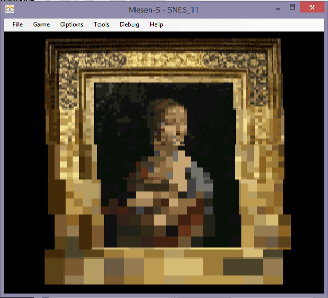
Example 4. Changing the Mosaic filter.
This is the simplest example. A single write to a single register. I haven’t discussed the Mosaic filter before, $2106 . The upper nibble is the mosaic amount (0 = normal, 1 = 2×2, etc up to $f = 16×16), and the lower nibble says which layers are affected. Sprites are never affected.
stz $4300 ;1 register, write once
lda #$06 ;mosaic
sta $4301 ;destination
ldx #.loword(H_TABLE6)
stx $4302 ;address
lda #^H_TABLE6
sta $4304 ;address

lda #1 ;channel 1
sta HDMAEN ;$420c
It waits 32 lines before increasing the mosaic value. There are bigger squares at the bottom. You probably wouldn’t use this exact HDMA effect in a game, but it is just an example of what is possible. You can change so many settings, even the BG mode $2105, which layers are active, change the location of a tilemap or tileset. I think you can even write new data to the VRAM (a little bit at a time).
.
.
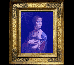
Example 5. Windows with Color Math.
(the next example page will talk more about Color Math registers)
Some of the coolest effects were done with this combination. We are adding a fixed color to tint the picture, and using the windows to shape the color box. If we made the HDMA table for the window more elaborate, it could be a circle, or any simple shape. We could change the table and make it grow or squish. The windows work the same as before, but we just needed to change the settings so that the window affects color math and nothing else.
lda #$20 ;Window 1 active for color, not inverted
sta $2125 ;WOBJSEL - window mask for obj and color
lda #$10 ;prevent outside color window, clip never,
;add fixed color (not subscreen)
sta $2130 ;CGWSEL - color addition select
lda #$3f ;color math on all things, add, not half
sta $2131 ;CGADSUB - color math designation
We are setting the color math to use only the fixed color, and not the subscreen. So, we need to set the color of the fixed color register $2132.
lda #$8f ;blue at 50%
sta $2132 ;COLDATA set the fixed color
This register (fixed color) is a bit complicated, I will explain it more on the next page, but the upper bits are the color selectors, and the lower 5 bits are for value. 8 is blue and $0f is for 15 (out of 31), or just above 50%. With color math addition (with the fixed color) turned on, it would color the entire screen blue. But, our HMDA window blocks out the effect for the top, sides, and bottom of the screen, leaving a blue box in the size/shape of the painting.
.
.
Here’s a YouTube video of these examples (video is old, doesn’t include the 5th effect)
.
IMPORTANT NOTE – the top most scanline is never drawn. It’s blank. At the end of that 0th scanline, it sends the first value of the HDMA tables, and then it sets the scanline count. The HDMA table looks like the scanline count is before the value to send, but it does it the opposite… it sends the value and then it waits. That means that the first value effects the very top of the visible screen.
The HDMA table resets at the end of v-blank. Automatically. Even if it didn’t complete the table because it was longer than the number of scanlines on screen, it jumps back to the 0th item on the HDMA table, and continues the next frame from the top of the table.
Also, a count of zero terminates the HMDA for the rest of the frame, but it still resets again, at the top of the next frame, and keeps going. If there is a value listed after the zero, it isn’t sent.
.
Links.
https://wiki.superfamicom.org/dma-and-hdma
https://wiki.superfamicom.org/grog’s-guide-to-dma-and-hdma-on-the-snes
.
